| TTN version: | TTNv3 |
| Activation: | ABP |
| Device Class: | Class A |
| Last updated: | January 23, 2023 |
This article provides instructions for using GPS Tracker as a TTN Mapper. If you don’t have a GPS Tracker, check out our GPS Tracker article.![]()
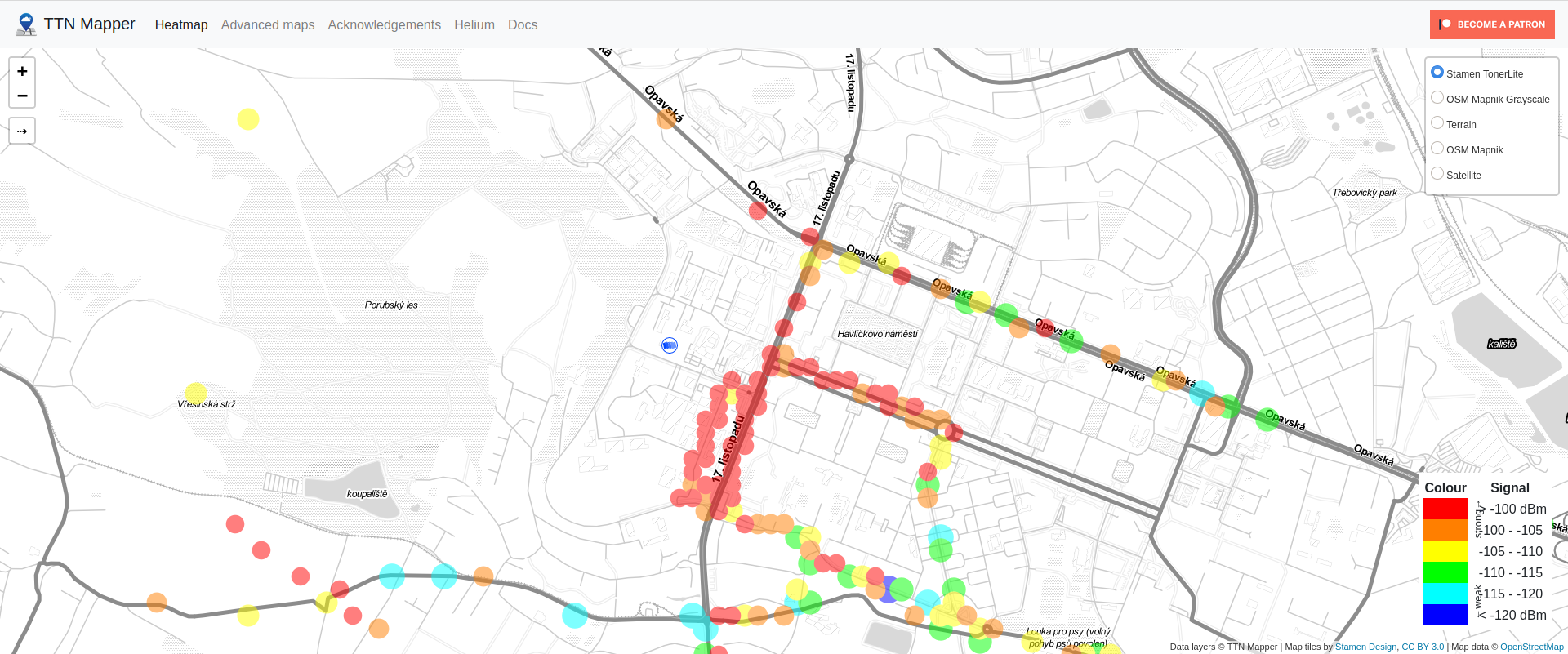
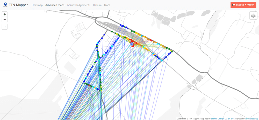
TTN Mapper is used to map The Things Network coverage. This is done by sending location information to the TTS. This device sends latitude, longitude, altitude and hdop to TTS every + -15 seconds. There is a TTN Mapper integration to contribute data to the coverage map. An example of a coverage map is below. You can find the public coverage map at ttnmapper.org.
Prepare
- GPS Tracker
- PC + micro USB cable
- Set up Arduino IDE
- Set up MCCI LoRaWAN LMIC library
Arduino IDE setup
- Run Arduino IDE.
- In the Arduino IDE Library Manager search TinyGPSPlus by Mikal Hart and install it.
- Download as ZIP this Low-Power library by Rocketscream.
- In the Arduino IDE Sketch -> Include Library -> Add .ZIP Library… choose downloaded ZIP.
The Things Stack setup
- Login on The Things Network.
- Click on your username and choose Console.
- Select a network cluster.
Add application
- Go to applications.
- Click on button + Create application.
- Write something into Application ID.
- Click on button Create application.
Add end device
- In your application click on button + Register end device.
- Input Method – Choose Enter end device specifics manually.
- Frequency plan – Europe 863-870 MHz (SF9 for RX2 – recommended)
- LoRaWAN version – LoRaWAN Specification 1.0.3
- Click on Show advanced activation, LoRaWAN class and cluster settings
- Activation mode – Activation by personalization (ABP)
- Additional LoRaWAN class capabilities – None (class A only)
- Deselect – Use network’s default MAC settings
- Rx1 data rate offset = 0
- Rx1 delay = 1
- Resets frame counters – Enabled
- Rx2 data rate = 3
- Rx2 frequency = 869,525 MHz
- Add Frequency = 868100000
- Add Frequency = 868300000
- Add Frequency = 868500000
- Add Frequency = 867100000
- Add Frequency = 867300000
- Add Frequency = 867500000
- Add Frequency = 867700000
- Add Frequency = 867900000
- DevEUI – Generate
- Device address – Generate
- AppSKey – Generate
- NwkSKey – Generate
- End device ID – here you can name your device
- After registration – View registered end device
- Click on button Register end device
- Click on General settings
- Network layer – Expand
- Click on Advanced MAC settings
- Desired Rx1 delay = 1
- Adaptive data rate (ADR) – Dynamic mode
- Click on button Save changes
Payload formatters
- In TTS -> Applications -> YourAppName -> Payload formatters -> Uplink change Formatter type to Custom Javascript formatter.
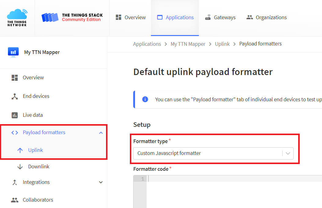
- To Formatter code copy and paste code bellow:
function decodeUplink(input) {
   var data = {};

   data.latitude = (input.bytes[0] << 16) + (input.bytes[1] << 8) + input.bytes[2];
   data.latitude = (data.latitude / 10000)

   data.longitude = (input.bytes[3] << 16) + (input.bytes[4] << 8) + input.bytes[5];
   data.longitude = (data.longitude / 10000)

   data.altitude = (input.bytes[6] << 8) + input.bytes[7];
   data.altitude = data.altitude / 10

   data.hdop = input.bytes[8] / 10;

   return {
      data: data,
      warnings: [],
      errors: []
   };
}
- Save changes.
Program for sending coordinates to TTS
We have prepared program for sending latitude, longitude, altitude and hdop to TTS every +-15 seconds.
- Copy and paste GPS Tracker program to your Arduino IDE.
- In program replace NWKSKEY, APPSKEY and DEVADDR with keys of your end device registred in TTS. Keys are in TTS -> Applications -> YourAppName -> YourEndDeviceName -> Overview -> Session information.
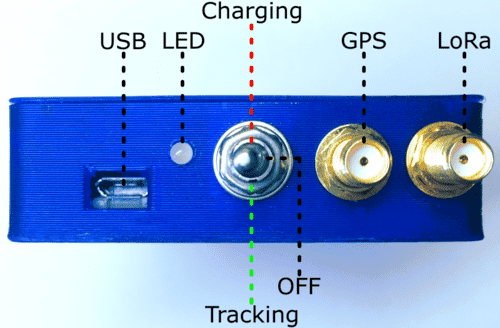
- Set the switch on the GPS Tracker to the middle (OFF) position.
- Connect Adafruit Feather 32u4 using micro USB cable to your computer.
- In Arduino IDE click on Upload button to upload program to your Adafruit Feather 32u4.
- The LED should start flashing green and red.
- Set the switch on the GPS Tracker to the Tracking position (as shown bellow).
- The LED should start flashing green.
- If the GPS data are valid, then the LED flashes green at a longer interval and the data are sent to the TTS.
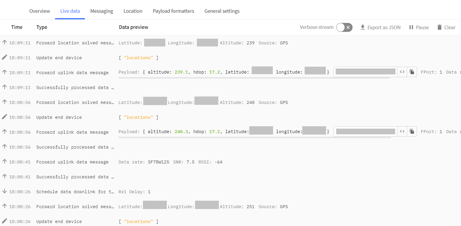
- In TTS -> Applications -> YourAppName -> YourEndDeviceName -> Live data you should every +-15 seconds see this:
- For more information on GPS Tracker operating modes, see the Operating Modes section.
TTN Mapper Integration
There are two types of integration – Experiment and Main map contribution. Both are described below.
The TTN Mapper documentation says:
Logging to the main map should only be done from roughly 0.5m-2m above ground level. “Ground level” should be interpreted as any place easily accessible by a human – or any place where an IoT device would commonly be installed. The top of a skyscraper is only acceptable if the skyscraper has a viewing deck that is publicly accessible. Man made hills and natural mountains are acceptable. The roof of a car or small delivery truck is fine. The roof of a bus or 14 wheeler truck is not as that is not a average acceptable height at which a sensor will be installed. The dashboard of a truck or bus is however roughly 2m above ground and therefore acceptable.
TTN Mapper Integration – Experiment
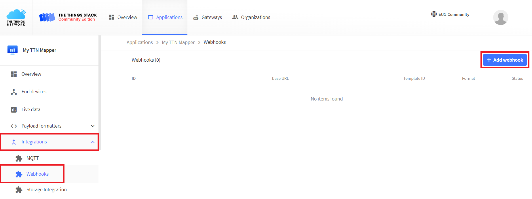
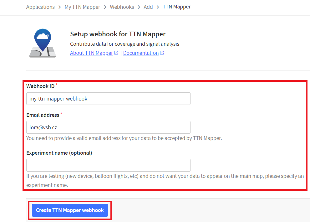
- In TTS -> Applications -> YourAppName -> Integrations -> Webhooks click button +Add webhook.
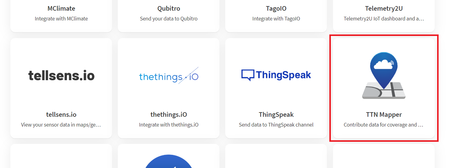
- Select TTN Mapper
- Write something in the Webhook ID and enter your Email address. If you are testing new device and don’t want your data to appear on the main map, write something in the Experiment name (our case). Then click on button Create TTN Mapper webhook.

TTN Mapper – Show Experiment Data
- On the TTN Mapper website, select Advanced Maps.
- Scroll down to section Show Experiment Data.
- Write your Experiment name from above.
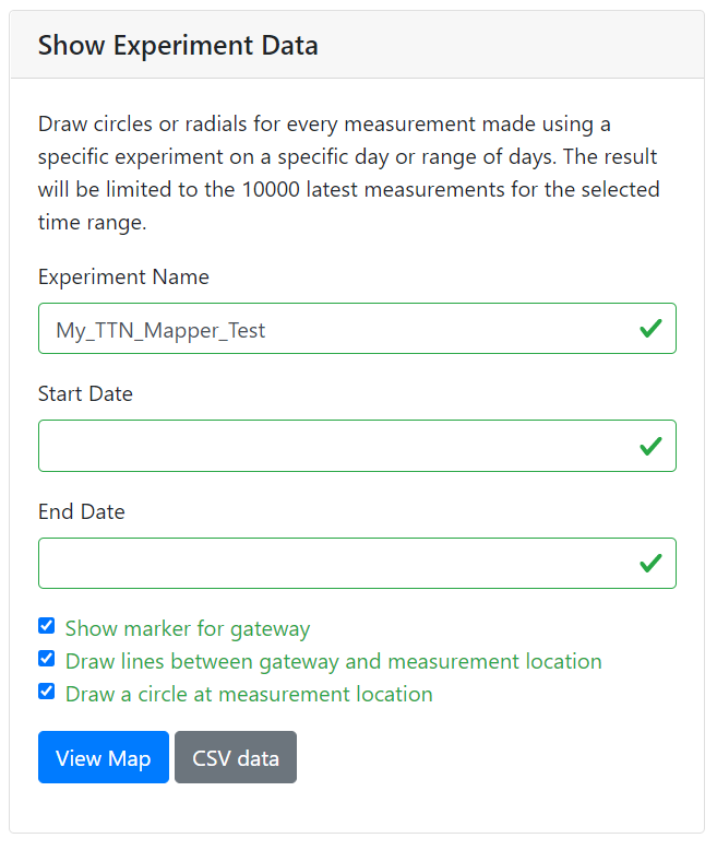
- Click on button View Map.
- An example map is shown below.
- If you are satisfied with the result of the experiment and meet the conditions for TTN mapping (above in section TTN Mapper Integraton), you can start contributing to the Main map.
TTN Mapper Integration – Main map
- If you have performed the TTN Mapper Integration – Experiment section, add a new Application and a new End device. Then reprogram your GPS Tracker with the new keys. (Repeat The Things Stack setup and Program for sending coordinates to TTS from above.)
- In TTS -> Applications -> YourAppName -> Integrations -> Webhooks click button +Add webhook.
- Select TTN Mapper
- Write something in the Webhook ID and enter your Email address. Leave the Experiment name blank. Then click on button Create TTN Mapper webhook.
- The newly received data will appear on the TTN Mapper Main Map (This may take up to 24 hours).
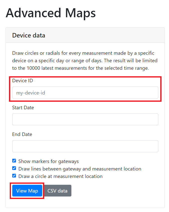
TTN Mapper – Show Device data
- Real-time data can be viewed in Advanced Maps on the TTN Mapper website.
- In the Device Data section.
- Write your end Device ID.
- Click on button View Map.