| TTN version: | TTNv3 |
| Board: | Adafruit Feather M0 |
| Activation: | OTAA |
| Device Class: | Class A |
| Transmission: | Duplex Data Transmission |
| Last updated: | April 26, 2023 |
Warning: This article is for informational purposes only and is not a guide. If you assemble the device, you do so at your own risk. We are not responsible for any damage, injury or loss of life! The device works in the electrical grid in the Czech Republic, whose parameters and standards may differ from the grid parameters in your country.
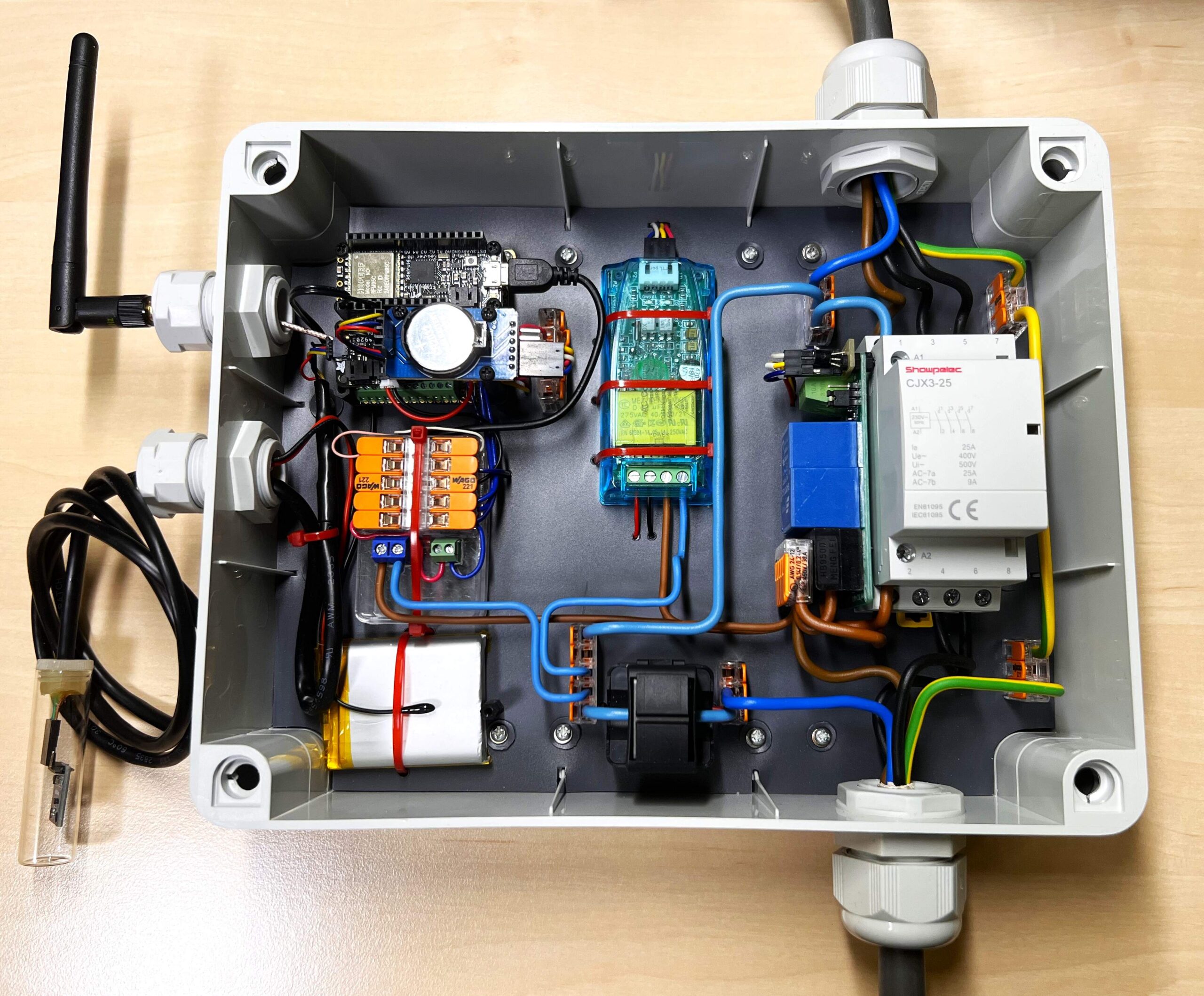
This article describes the design of a device that can switch, for example, the lights in a small parking lot or lights around a house based on lighting intensity, time settings, light intensity at selected times, or sunrise and sunset times. The device also functions as a measuring device that measures light intensity (with a BH1750 sensor), voltage and frequency of the power line (with a PZEM-004T-100A measuring device). When the device is switched on, it measures the electrical energy consumption, current, active power and power factor of the switched device (also with the PZEM). Furthermore, the voltage, state and temperature of the battery that powers the device during a power failure (by the LC709203F module) and the temperature of the RTC are measured. The device uses the Adafruit Feather M0 RFM95 LoRa Radio and the components listed below. 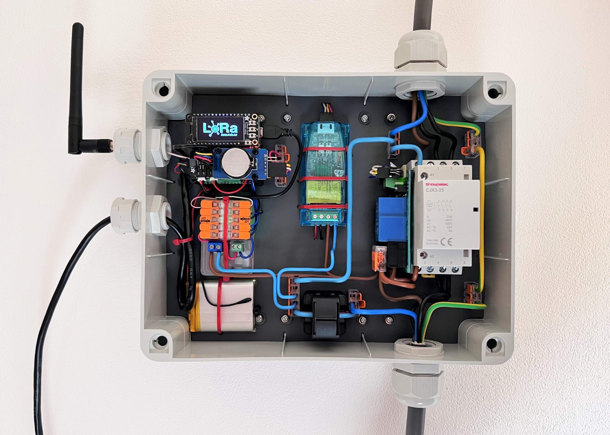
Content
- Main features
- Components
- Assembly
- Arduino IDE setup
- The Things Stack setup
- Program
- Telegraf, InfluxDB & Grafana
- MSD control via downlinks
Main features
- The device sends measured data using uplinks to the TTS network.
- When switching a device powered from three phases (400 V), the PZEM only measures the voltage and frequency of the phase from which the multifunctional switching device is powered.
- When the device is switched on, it measures the electrical energy consumption, current, active power and power factor of the switched device.
- The device sends information about its set configuration to the TTS network.
- The multifunction switching device is set using received downlinks from the TTS network.
- A Python program, a Python script and a Grafana panel plugins are available for the Multifunctional switching device, with which this device can be easily set up via the TTS network.
- Data sent in both uplinks and downlinks use Cayenne LPP formatting (with added data types and custom added type for time).
- Device setup using downlinks is password protected.
- Traffic is divided using FPort into measured data sent with FPort 1 and downlink configuration and configuration information is sent in FPort 2.
- It is possible to set how often and what data will be sent in uplinks.
- It is possible to set how many samples of measured data will be used to calculate the resulting averages, which will be sent in the uplink.
- It is possible to set the threshold and the safe zone of light intensity, for switching according to the light intensity.
- It is possible to set up to three switch-off and three switch-on times.
- The device automatically calculates the sunrise and sunset times according to the selected coordinates.
- The ability to remotely change the working modes of the device or remotely restart it.
- The device automatically sets the date and time obtained from the TTS network.
- All set values are stored in the EEPROM memory, so that the device does not have to be set again after a restart or an unexpected shutdown.
- The device sends information about device errors and incorrectly entered settings.
- In the event of a power failure, the device is powered by the battery.
Components
Box
- Box Gewiss GW44208 – IP56 – 240x190x90
- DIN rail 3,5 cm
- 2x cable gland Pg 13.5
- 2x Flexible Polymer Cable Gland
- 2x cable gland M25x1.5
- Plastic flat sheet plate 3 mm thick (dimensions according to the bottom of the box, white)
- Modeling pad A3 (1-991, Karton P+P spol. s.r.o.)
- 2x Bolt (short) and nut to the DIN rail
- 12x Screw 2.5 mm, length 10 mm
- 12x spring washer on screw
“Cube”
- Black Nylon Machine Screw and Stand-off Set – M2.5 Thread
- FeatherWing Doubler
- Terminal Block kit for Feather – 0.1″ Pitch
- Adafruit Feather M0 RFM95 LoRa Radio
- Adafruit LC709203F LiPoly / LiIon Fuel Gauge and Battery Monitor
- 10K Precision Epoxy Thermistor – 3950 NTC
- RTC Real Time Clock DS3231 AT24C32
- uFL SMT Antenna Connector
- SMA to uFL/u.FL/IPX/IPEX RF Adapter Cable
- NiceRF SW868-ZD115 Antenna 2.15dBi 11cm 868MHz
- GeB LiPol Battery 104050 2500mAh 3.7V JST-PH 2.0
- A cable with a Micro-USB B connector that will be cut later
- Adafruit FeatherWing OLED – 128×64 OLED (not implemented in the v1.0 code)
Light intensity sensor
- Light intensity sensor BH1750
- Glass vial with lid (SPOFA)
- 26AWG / 4PRS UTP Patch Cable EEKSONG
- Assorted Shrink Tubing
5V Power source
- Power supply module WX-DC12003 230V/5V 700mA
- CZM 5/2 (ARK 500/2) 10x10x7.5mm 5mm small
- PCB terminal block 2P CY350-3.5-2P RM3.5mm, green
- Box (from pins) 5.5×3.5×1.5 cm
Electrical mains part
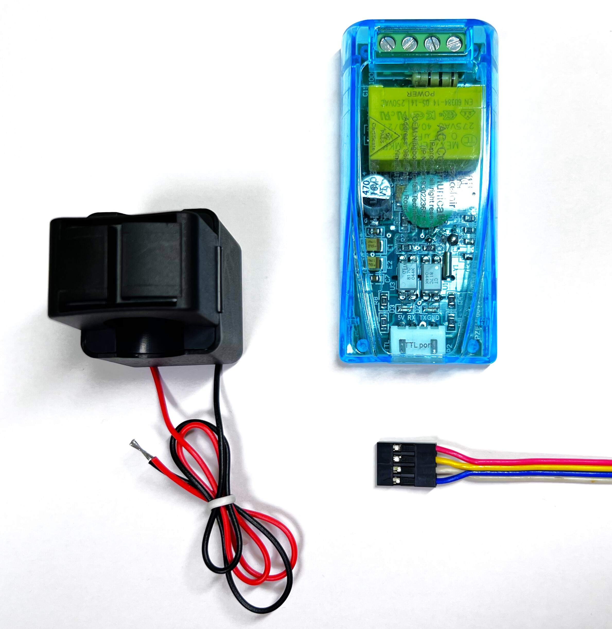
- PZEM-004T-100A-V3.0
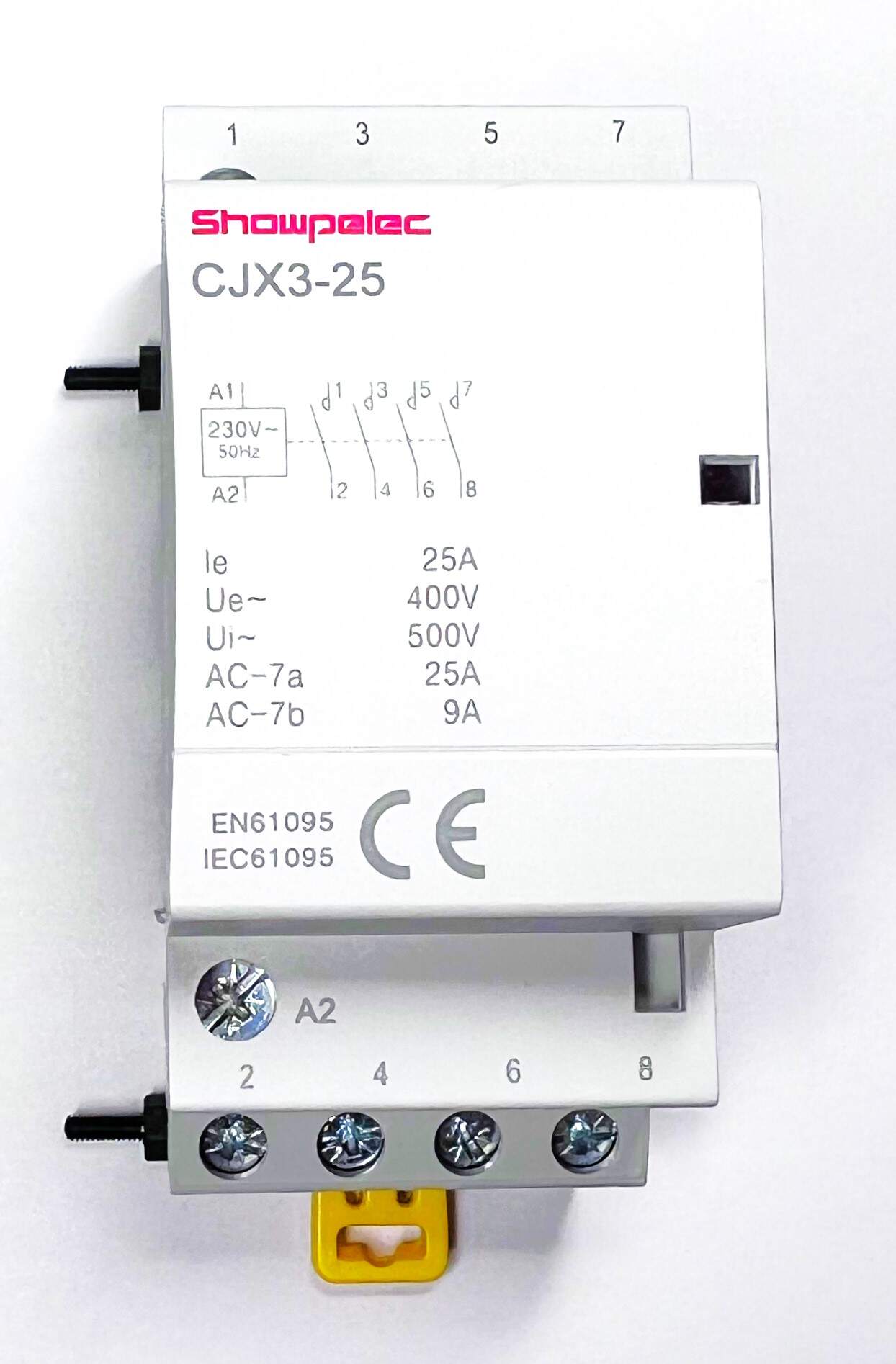
- Contactor CJX3-25 230V/25A 4P
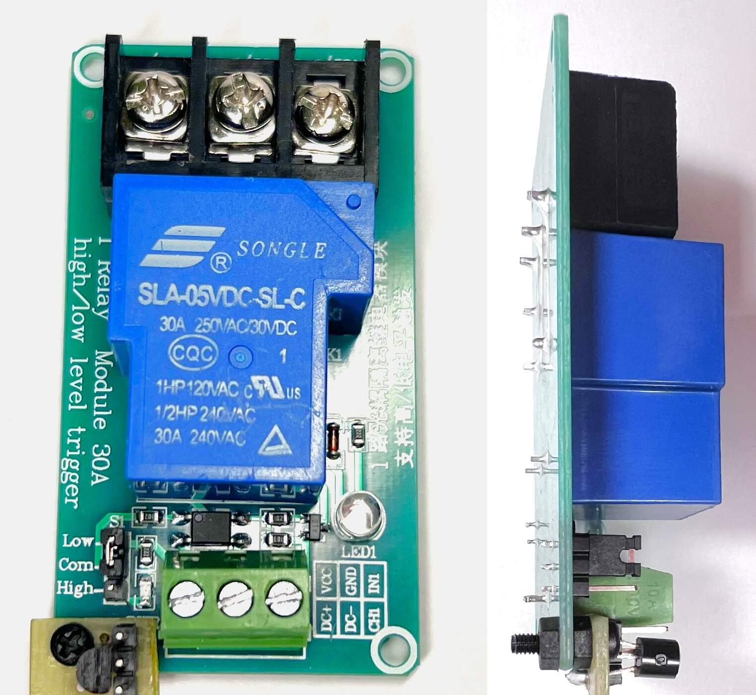
- 1-channel 5V relay module, High-Low 250VAC 30A
- NPN Transistor BC550C
- 50x70mm PCB prototype board
Common and other
- Dupont connectors 1-8pin with 2.54mm pitch for PCB
- 2m DuPont wire
- STEMMA QT – 20 cm
- 15x 100 mm cable ties
- 4x COMPACT Splicing Connector Wago 221-413
- 5x COMPACT Splicing Connector Wago 221-415
- Wires with a cross-section of 2.5 mm²
Tools
- Centropen OHP Permanent marker 2636 F
- UHU SUPER GLUE MINIS 3 x 1 g
- Soldering iron and solder
- Snap-off knife
- Drill and drill bits
- A set of screwdrivers
- Pliers
- Hot melt glue gun
- PC + micro USB cable
Assembly
The following section describes the procedure for connecting and assembling the device according to the electrotechnical diagram of the multifunctional switching device below.
Note: When choosing a connection with a measuring coil, the PZEM measuring device is connected according to the diagram. The PZEM input marked N is connected to the phase (Live wire) and the meter input L is connected to the neutral wire. Modules connected to the I²C bus will use the following addresses: RTC module address 0x57, LC709203F module address 0x0B and BH1750 module address 0x23.

“Cube” – First half
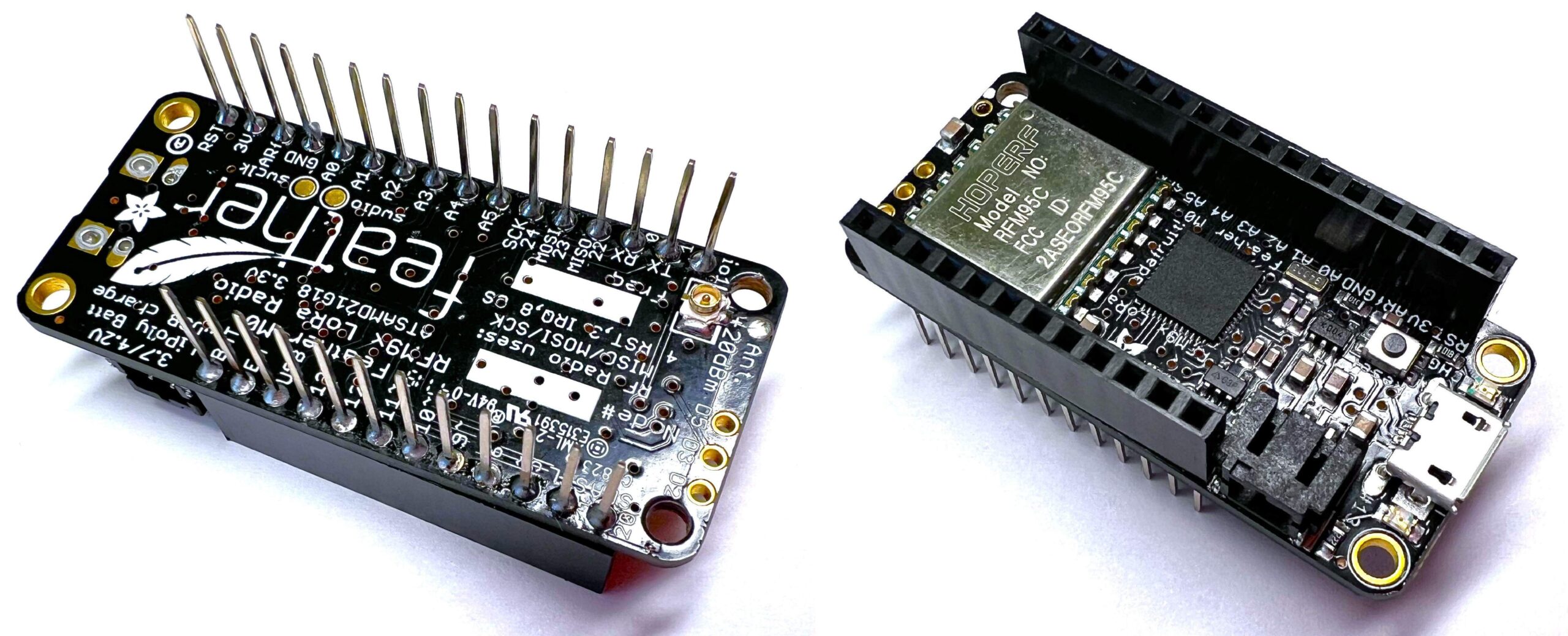
Adafruit Feather M0
- Solder the uFL SMT antenna connector to the Adafruit Feather M0 board.
- Next, solder the Stacking Headers for Feather (12-pin and 16-pin female headers) to the board (headers from FeatherWing Doubler).
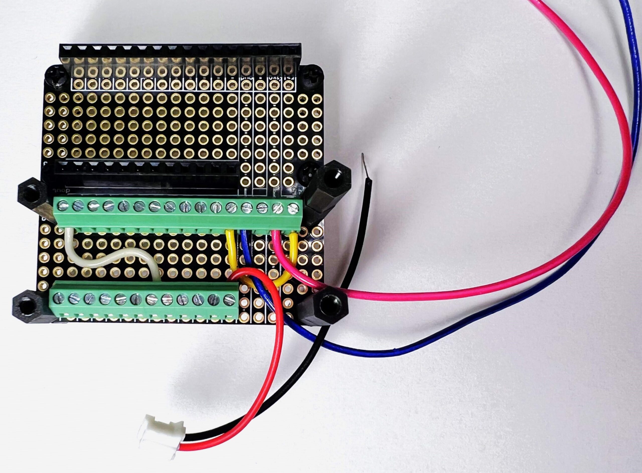
FeatherWing Doubler
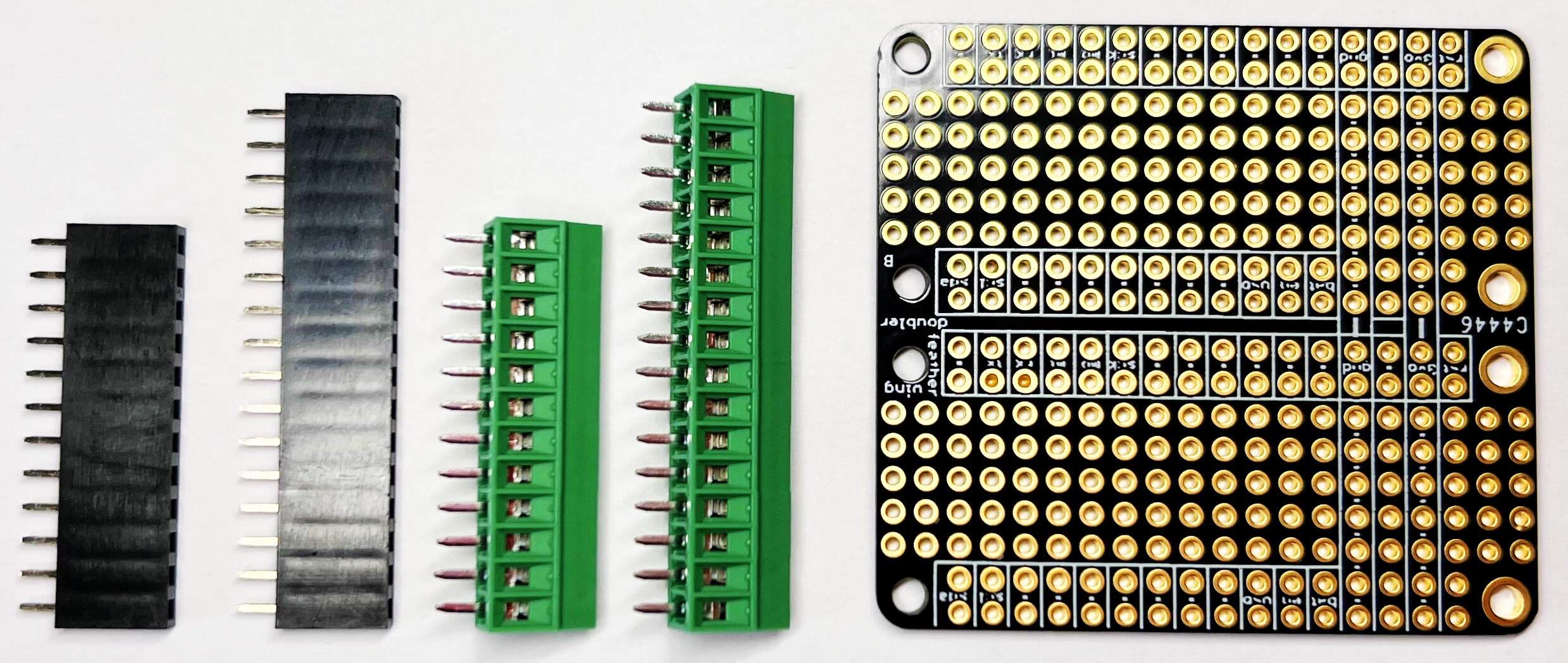
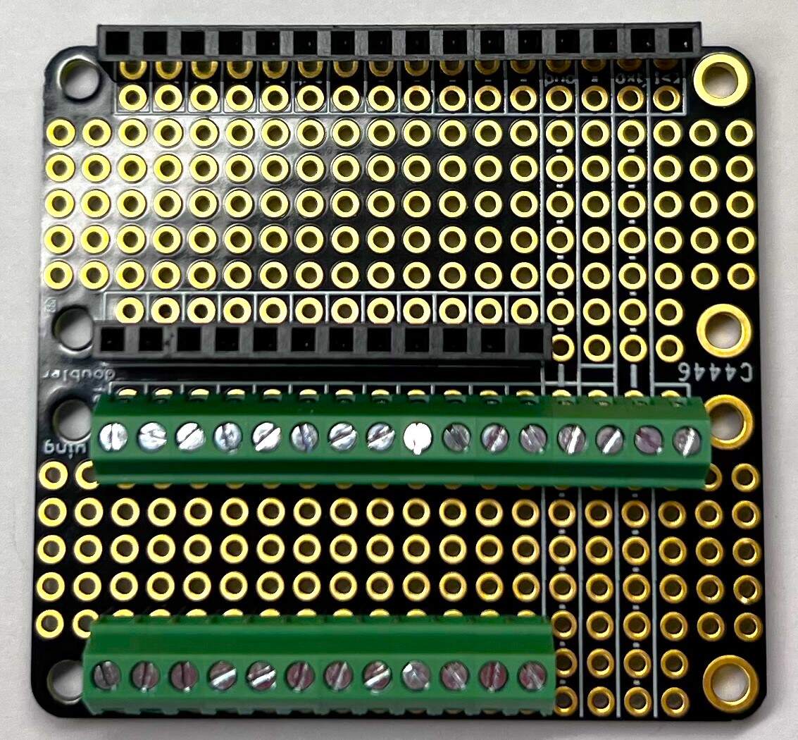
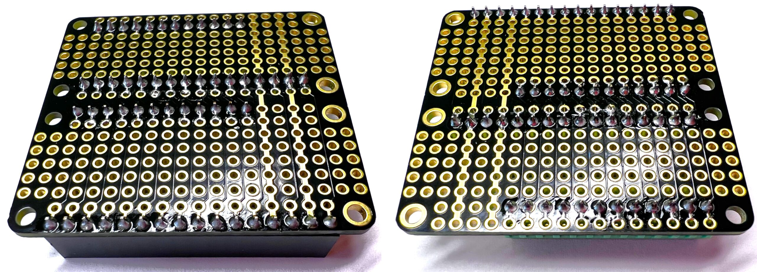
- Solder the Header Kit for Feather (12-pin and 16-pin Female Header Set) to the FeatherWing Doubler (headers from FeatherWing Doubler) as shown below.
- Next, solder the Terminal Block kit for Feather – 0.1″ Pitch to the FeatherWing Doubler as shown below.
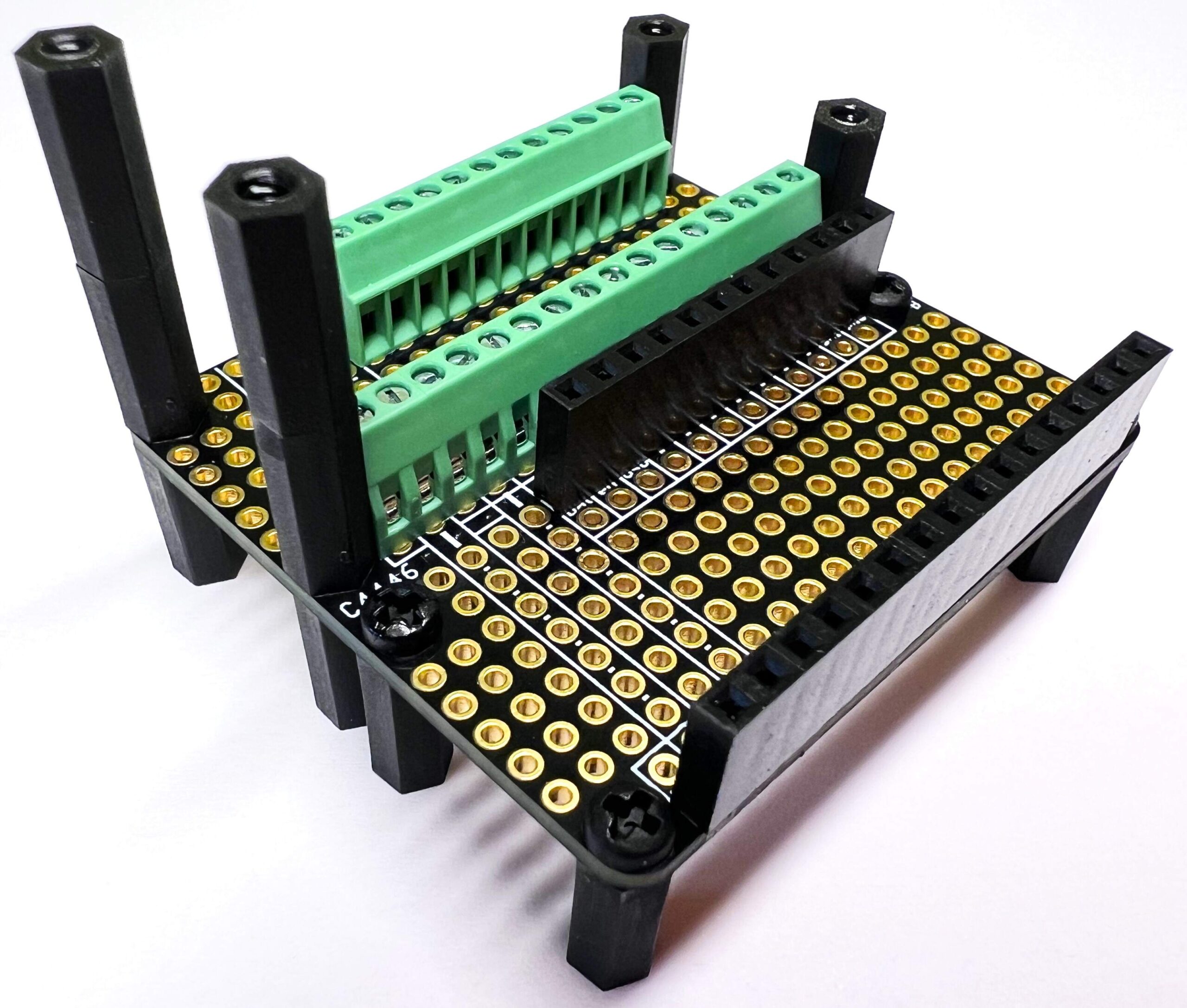
- From the Black Nylon Machine Screw and Stand-off Set, prepare 6 x 12mm long M-F hex standoff, 8 x 12mm long F-F hex standoff,
4 x M2.5 x 6mm Screw(Update note: Device tests have found that the vibration of the contactor opening and closing will shake the Adafruit Feather M0 board and cause it to reboot! This was solved by replacing the original 4x M2.5 x 6mm Screw in the pictures bellow with these 4 x 12mm long M-F hex standoffs, to which the Adafruit Feather M0 board is finally screwed (in the later steps of assembling the Cube).)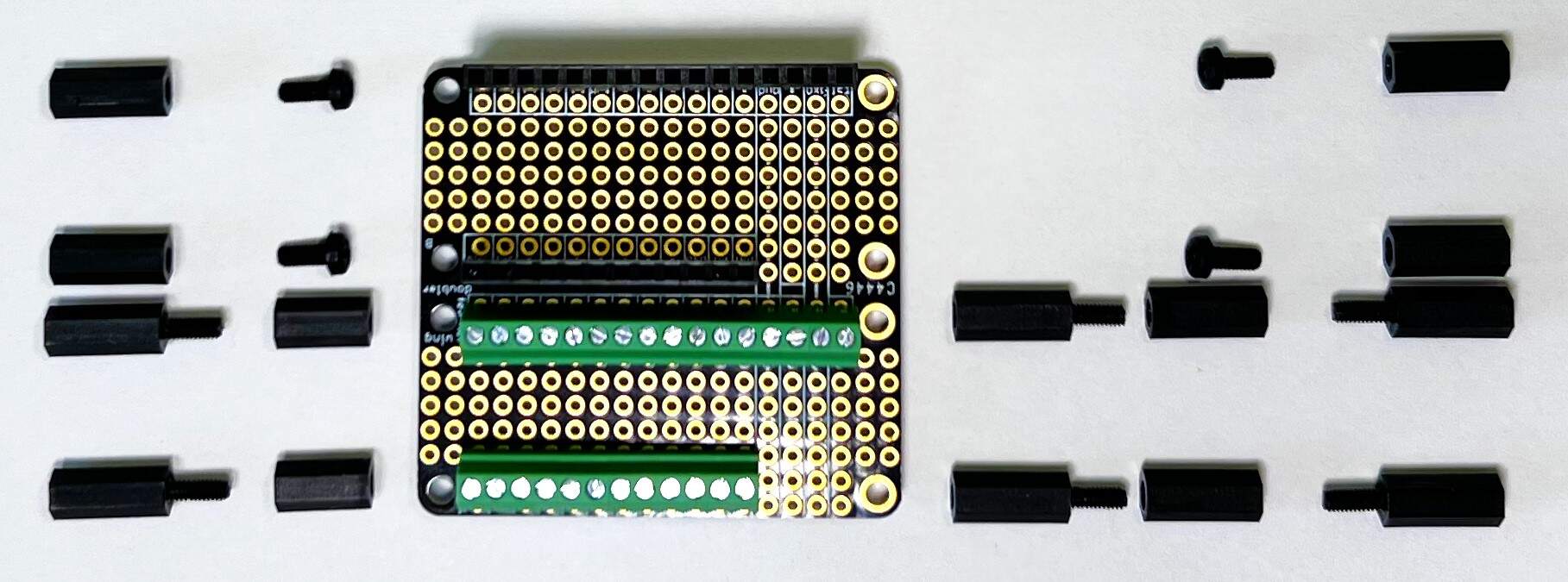
- Screw everything together as shown below.
- Screw the tinned wires to the Terminal Block kit as follows:
- Connect the red wire, which has a JST connector on the other end, to the BAT pin.
- Connect pin RST with a wire to pin A0 (yellow wire).
- Connect pin IO1 with a wire to pin 11 (because pin 6 uses the button on the display) (white wire).
- Screw a 15cm wire to the GND pin (blue wire).
- Screw a 15cm wire to the 3V pin (dark pink wire).
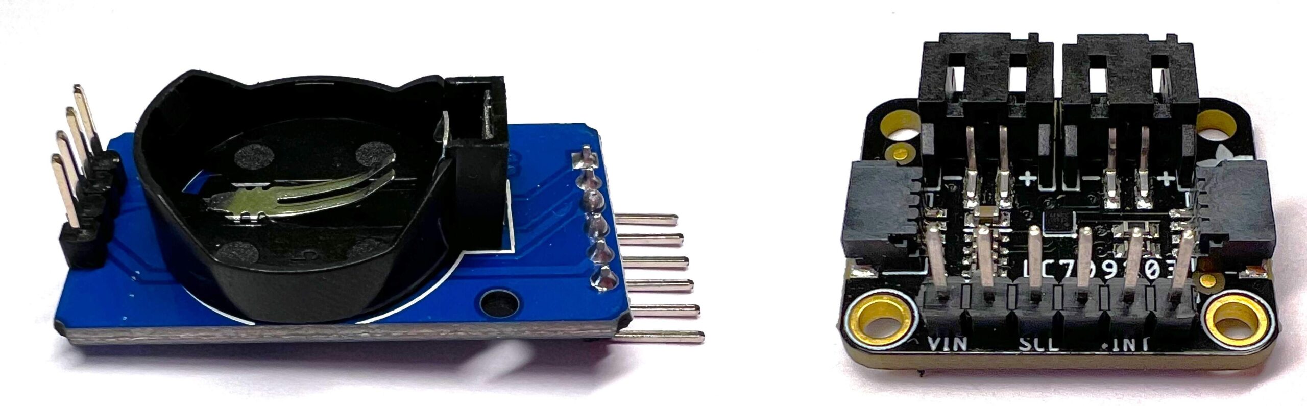
RTC and Adafruit LC709203F
- First, solder the Male Headers to the RTC and LC709203F.
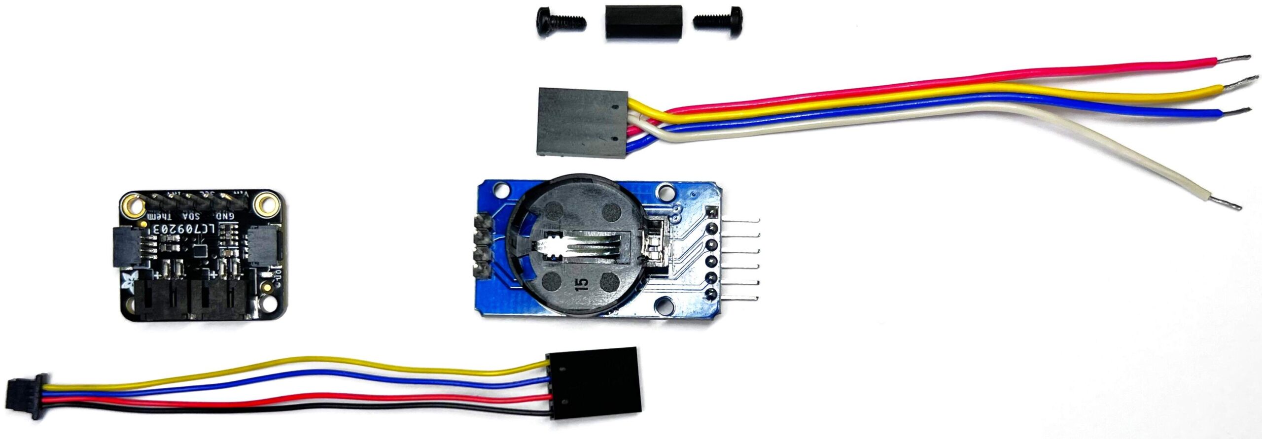
- Then prepare 2 x M2.5 x 6mm Screw, 12mm long F-F hex standoff, 2 x 4-pin DuPont connector, 4 x 15cm wire (DuPont wire), STEMMA QT – 20 cm.
- Attach the DuPont 4-pin connector to the DuPont cable. (Yellow – SCL, White – SDA, Red – VCC, Blue – GND)
- STEMMA QT – divide the 20 cm cable in half and attach a 4-pin DuPont connector to it according to the connection of the STEMMA QT connector and the order of the pins on the RTC module. (Yellow – SCL, Blue – SDA, Red – VCC, Black – GND)
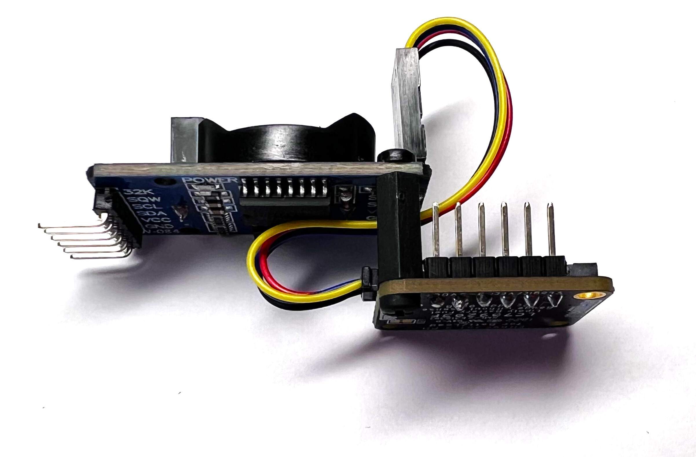
- Connect the modules with the created cable and screw them on top of each other using M2.5 x 6mm screws and 12mm long F-F hex standoff as shown in the picture.
Light intensity sensor
- First, solder the Male Headers that are bent at right angles to the BH1750 module.
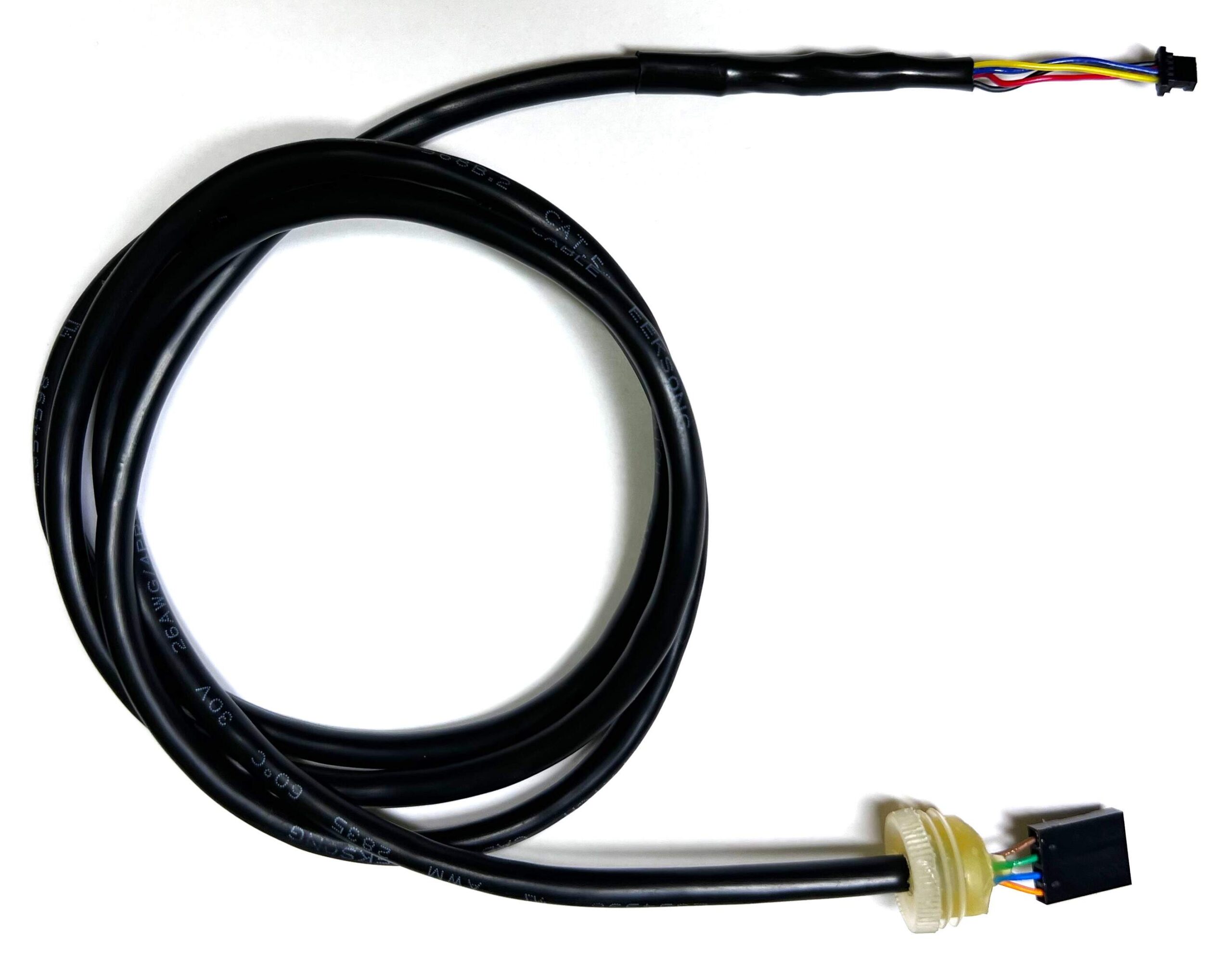
- Prepare the other half of the split 20cm STEMMA QT cable. Slide the heat shrink tubes onto the individual wires of the STEMMA QT cable and thread one heat shrink tube onto the UTP cable.
- Choose four wires from the UTP cable and write down their colors and the colors of the STEMMA QT cable wires to which they will be soldered.
- Solder the STEMMA QT cable to the UTP cable and gradually heat shrink the individual tubes.
- Make a small hole in the lid and thread the UTP cable through it as you can see in the picture below.
- Attach a 4-pin DuPont connector to the UTP cable according to the connection of the STEMMA QT connector and the order of the pins on the BH1750 module. (Yellow – SCL, Blue – SDA, Red – VCC, Black – GND)
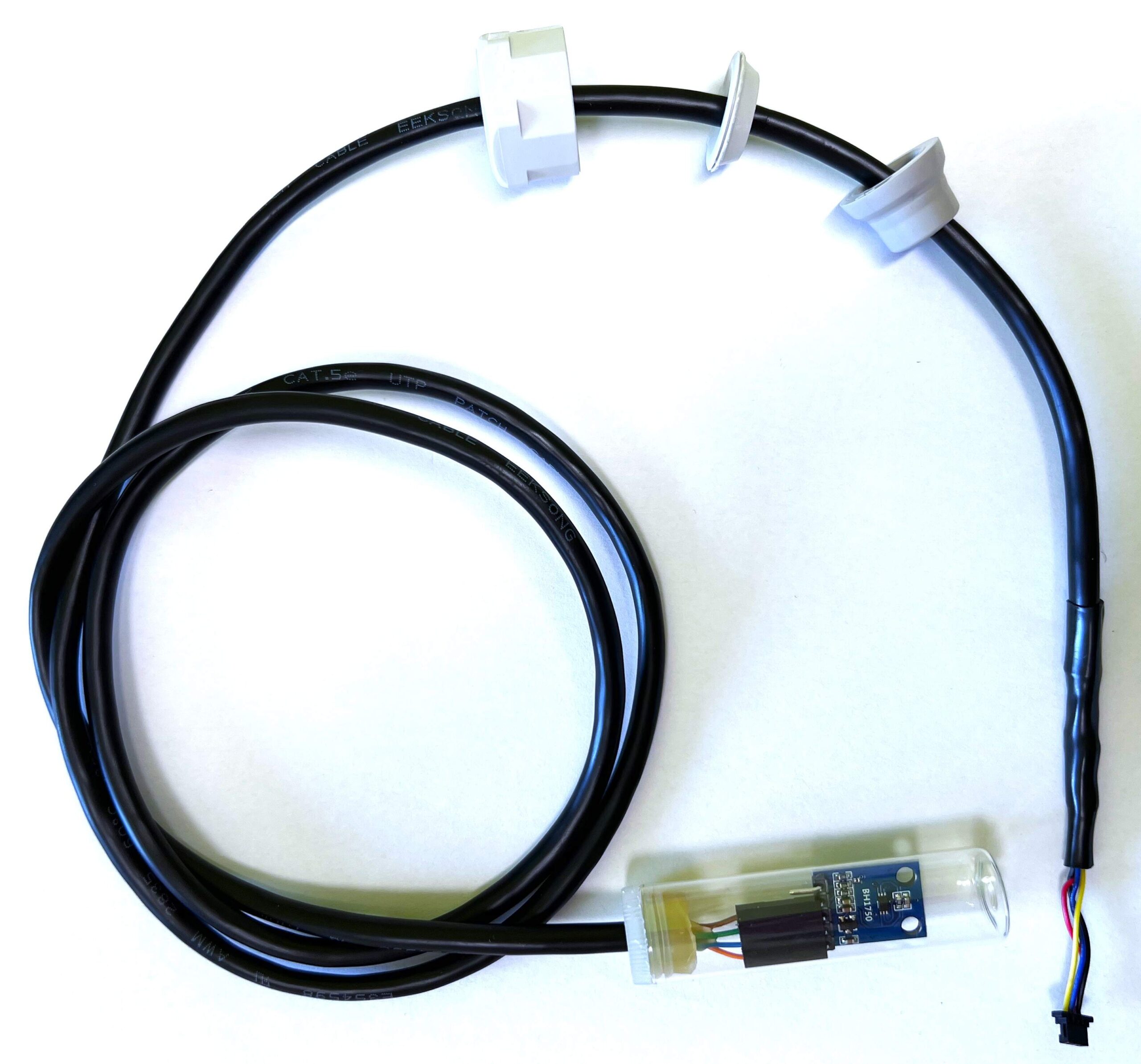
- Prepare a glass vial.
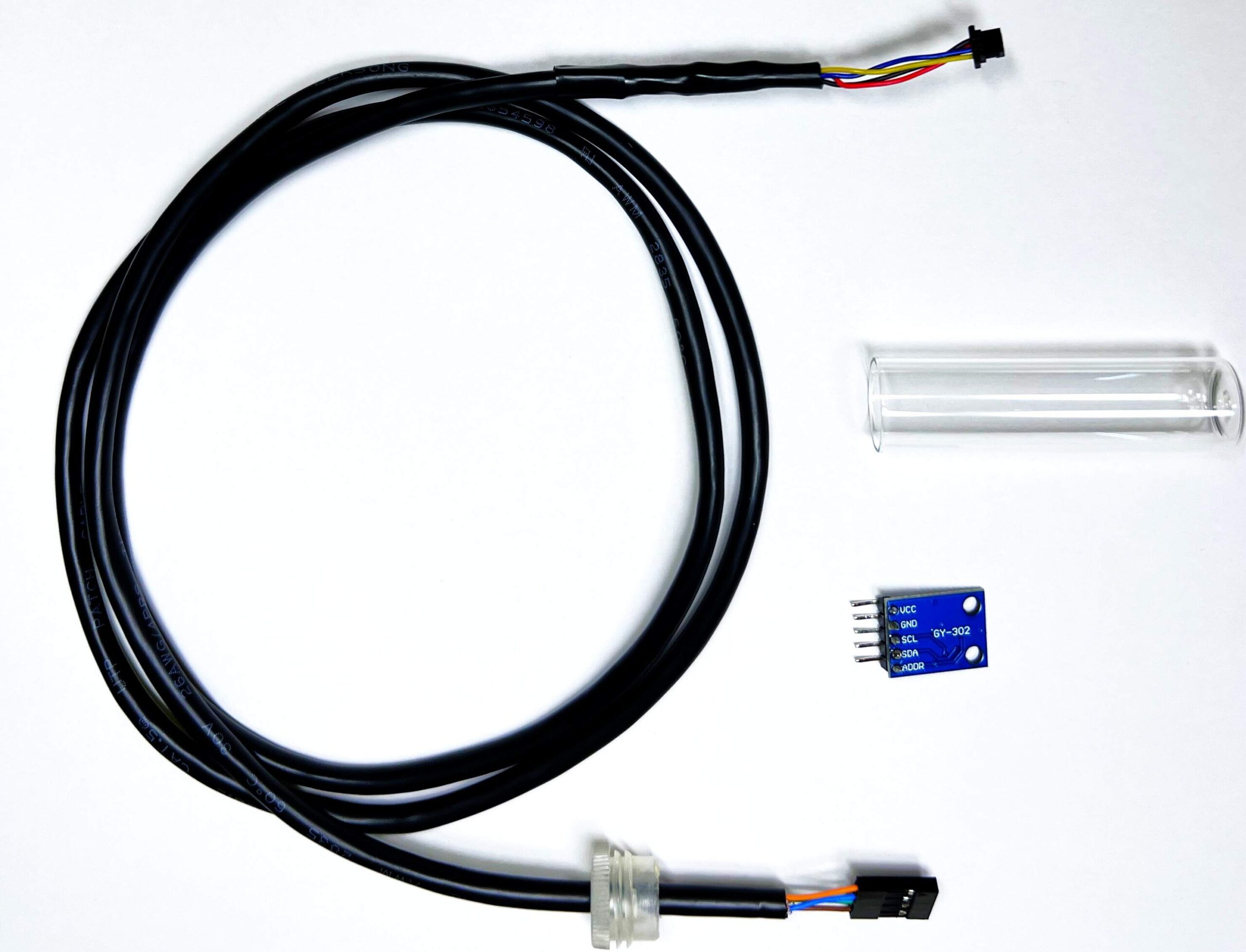
- Connect the BH1750 module to the DuPont connector, put it in the glass vial, close the lid and adjust the distance of the UTP cable inside the vial.
- Carefully remove the lid without moving the UTP cable and use a hot glue gun to glue it to the UTP cable. (remove the BH1750 module before gluing)
- Connect the BH1750 module back to the DuPont connector and close the vial with the lid.
- Trim the Flexible Polymer Cable Gland to fit the Pg 13.5 cable gland top nut.
- Then cut a small hole in the Flexible Polymer Cable Gland for the UTP cable.
- Put the top nut of the cable gland Pg 13.5 on the UTP cable, then the Flexible Polymer Cable Gland and finally the rubber seal from the cable gland Pg 13.5.
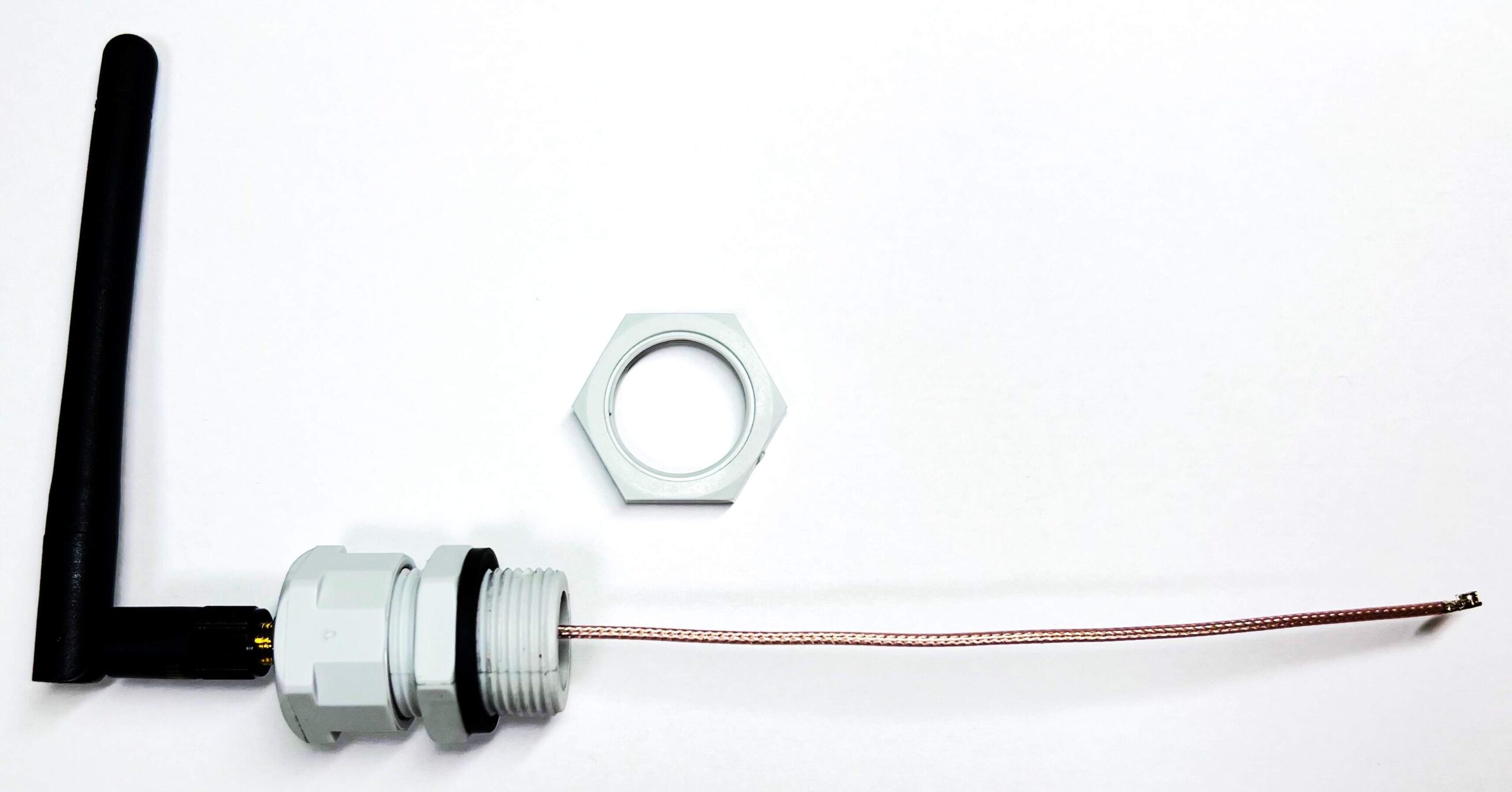
Antenna
- Prepare Flexible Polymer Cable Gland, cable gland Pg 13.5, SMA to uFL/u.FL/IPX/IPEX RF Adapter Cable and NiceRF SW868-ZD115 Antenna 2.15dBi 11cm 868MHz.
- Trim the Flexible Polymer Cable Gland to fit the Pg 13.5 cable gland top nut.
- Then cut a small hole in the Flexible Polymer Cable Gland for the Adapter Cable.
- Thread the Flexible Polymer Cable Gland onto the SMA and screw the nut firmly.
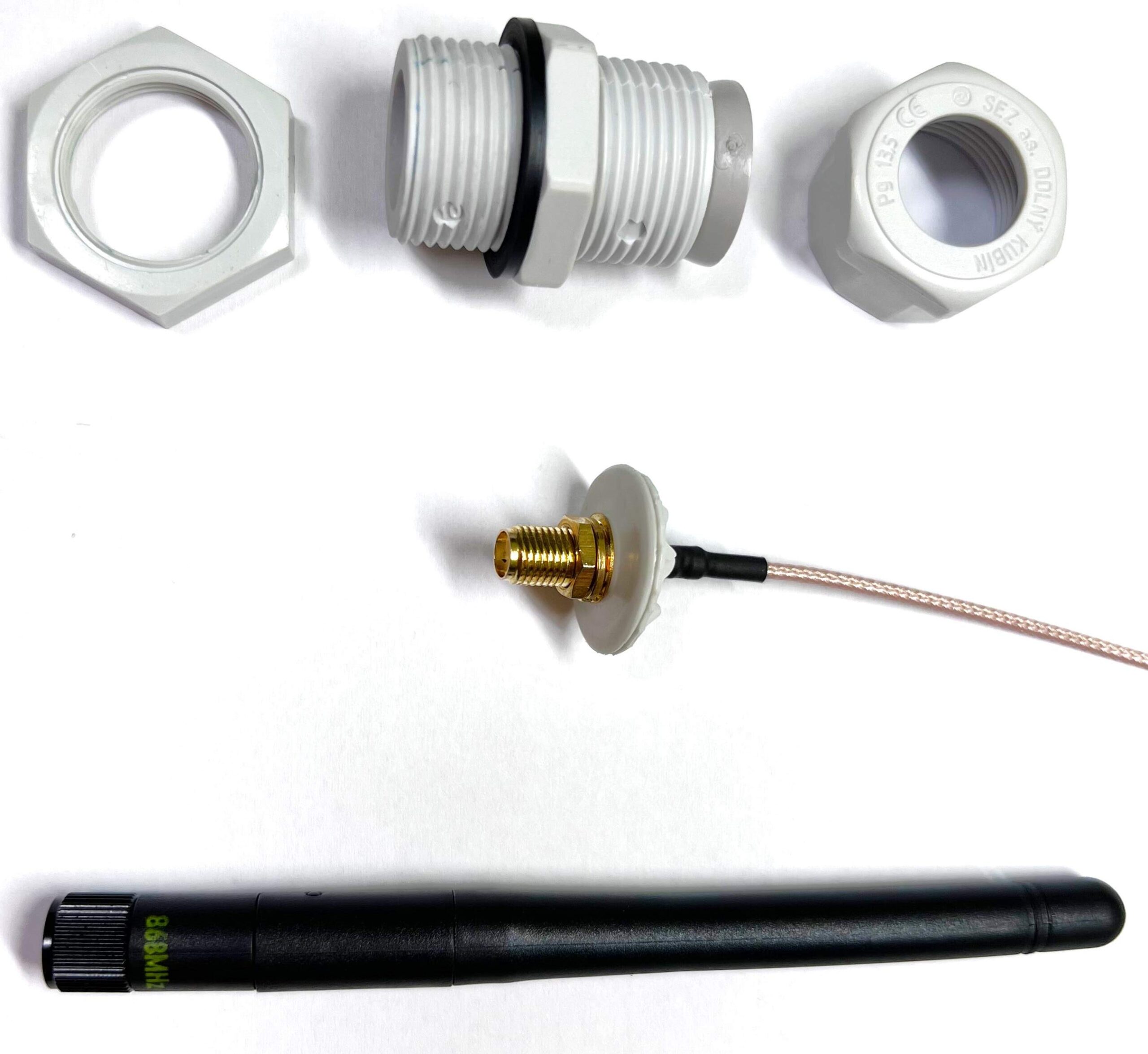
- Then push the Flexible Polymer Cable Gland all the way inside the Pg 13.5 cable gland top nut.
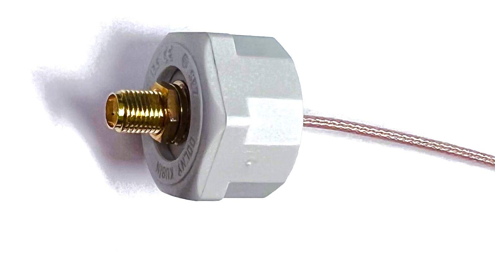
- Then put the rubber seal from the cable gland Pg 13.5 on the cable of the adapter and firmly screw the Pg 13.5 cable gland top nut to the rest of the cable gland Pg 13.5.
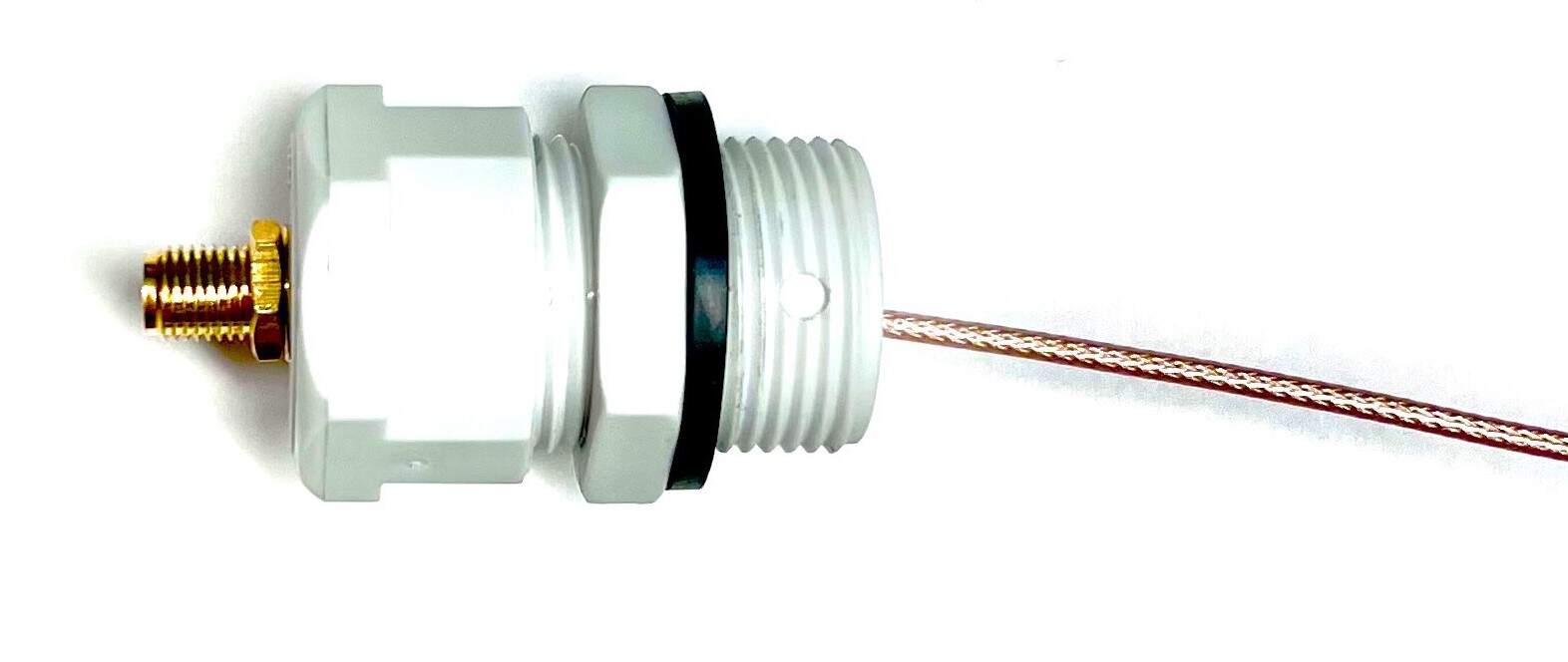
- Finally screw the antenna.
5V Power source
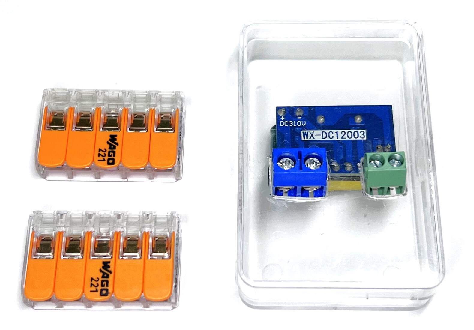
- Prepare Power supply module WX-DC12003, CZM 5/2 (ARK 500/2), PCB terminal block 2P CY350-3.5-2P, Box (from pins) and 2x COMPACT Splicing Connector Wago 221-415 and UHU SUPER GLUE MINI.
- Solder CZM 5/2 (ARK 500/2) and PCB terminal block 2P CY350-3.5-2P to the Power supply module WX-DC12003 as shown below.
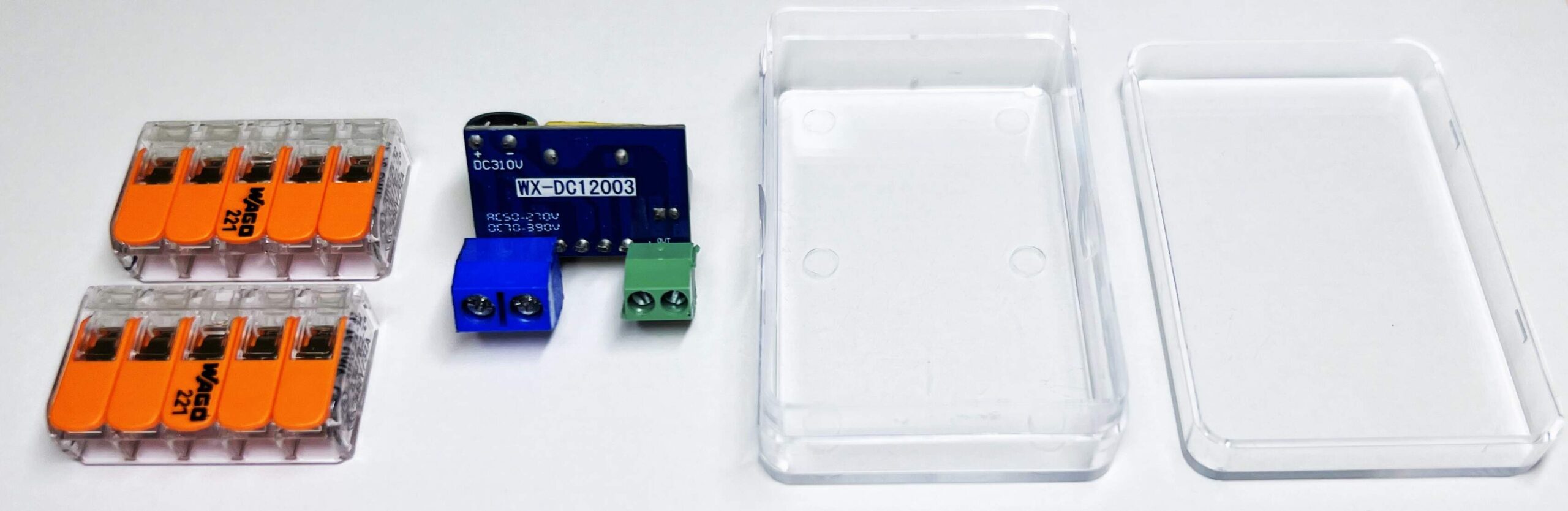
- In the upper part of the plastic box, make holes according to the size of the terminal blocks.
- Place the WX-DC12003 power supply module in the box, push the terminal blocks through the holes and close the box as shown below.
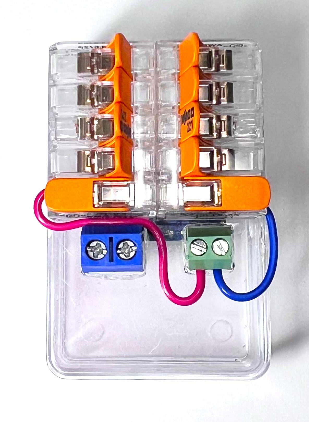
- Glue both COMPACT Splicing Wago 221-415 connectors to the top of the box using UHU SUPER GLUE MINI as shown below.
- Connect the glued Wago connectors to the power supply using two tinned wires as shown below.
Electrical mains part
PZEM
- Attach the 4-pin DuPont connector to the 4-wire 30cm DuPont cable as shown below. (On PZEM 5V – Red, Rx – Yellow, Tx – White, GND – Blue)
Contactor and relay
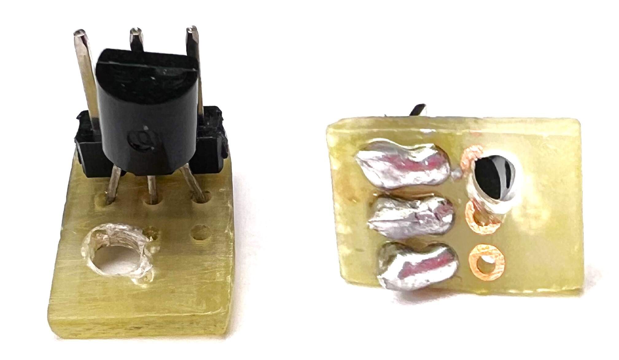
- Prepare the NPN Transistor BC550C, 50x70mm PCB prototype board and 3-pin Male Headers.
- From the 50x70mm PCB prototype board, cut a piece of board as you can see in the image below. (3×3 holes)
- Drill a mounting hole into the cut piece of board as shown below.
- Then solder the NPN Transistor BC550C and 3-pin Male Headers to this cut piece of board so that one pin of the transistor is connected to one pin of the Male Headers. Do this for all transistor pins.
- Thread the M2.5 x 10mm screw through the board and screw it in tightly with the M2.5 hex nut.
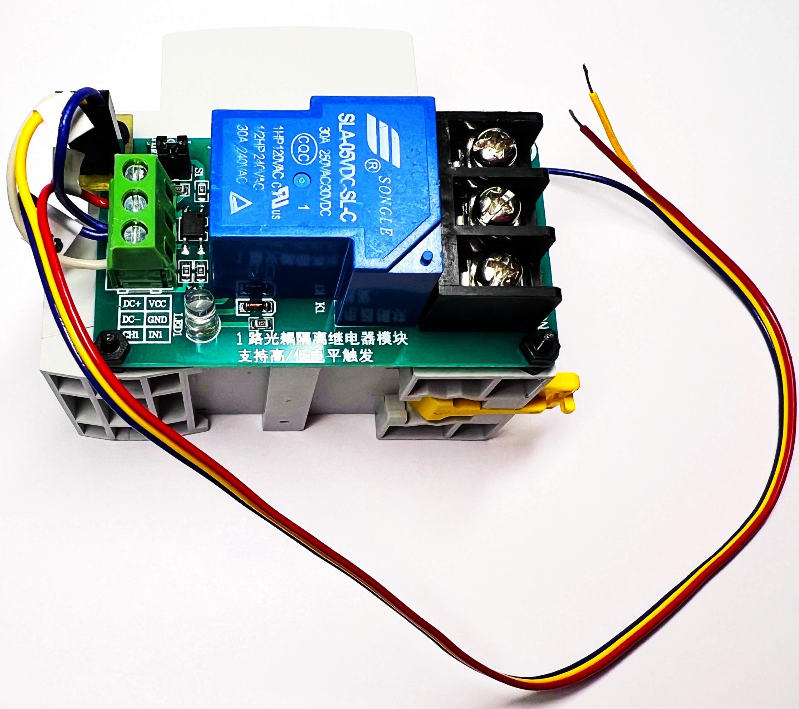
- Next, thread the screw through the mounting hole on the 1-channel 5V relay module, High-Low 250VAC 30A and tighten firmly with the M2.5 hex nut.
- Remove the protruding part of the screw with combination pliers.
- Check that the jumper on the Relay module is in the Com-Low position.
- Attach the center pin of the 3-pin DuPont connector (transistors Base) to the center (yellow) wire of the 3-wire 30cm DuPont cable as shown below.
- Then attach the pin of the 3-pin DuPont connector to a separate short (blue) wire on the side where the Emitter of the transistor will be connected (to GND).
- Then attach the last pin of the 3-pin DuPont connector to a separate short (white) wire on the side where the Collector of the transistor will be connected (to CH1 of the relay module).
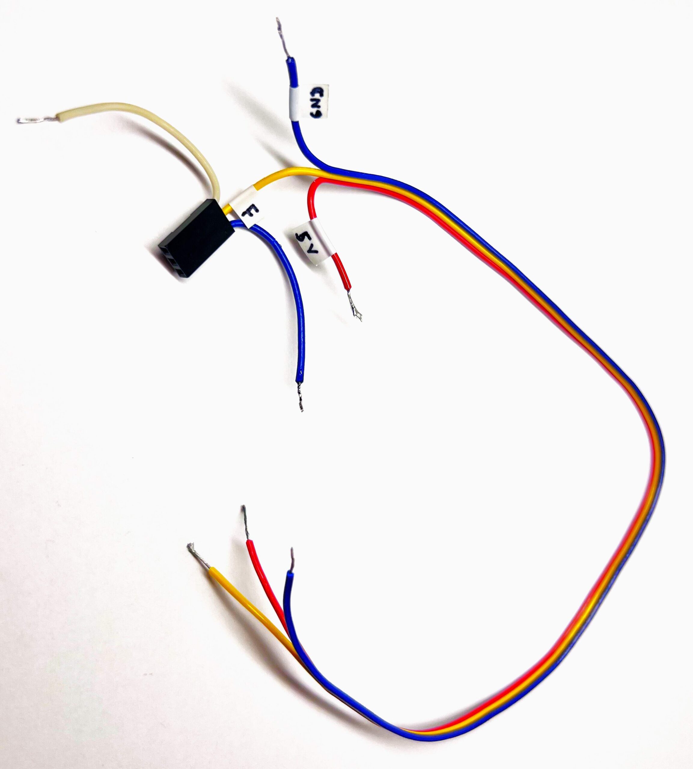
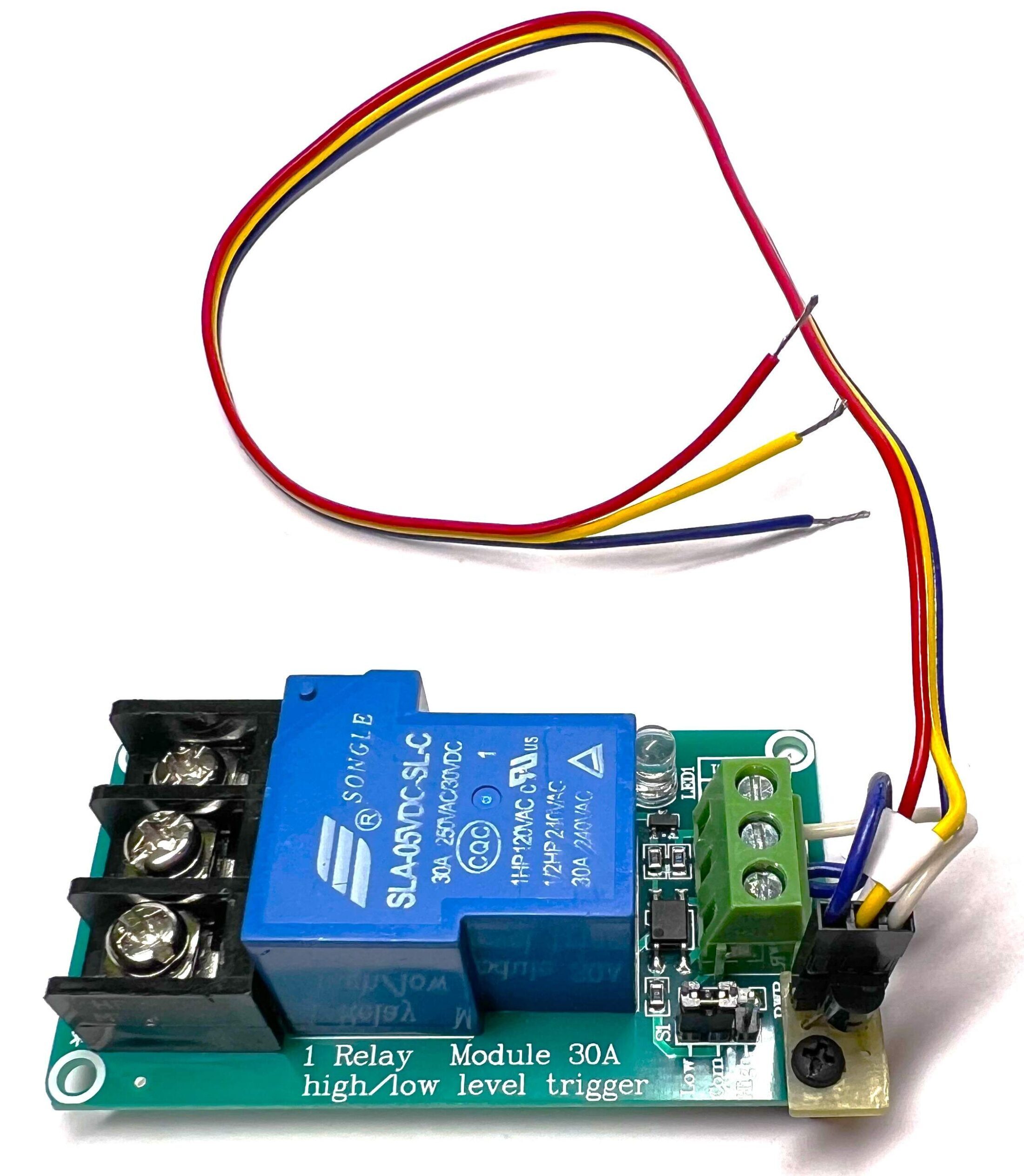
- Connect the DuPont connector to the 3-pin Male Headers of the transistor module. (blue – emitter, yellow – base, white – collector).
- Connect the two blue wires to the DC- terminal of the relay module, the red wire to the DC+ terminal, the white wire to the CH1 terminal.
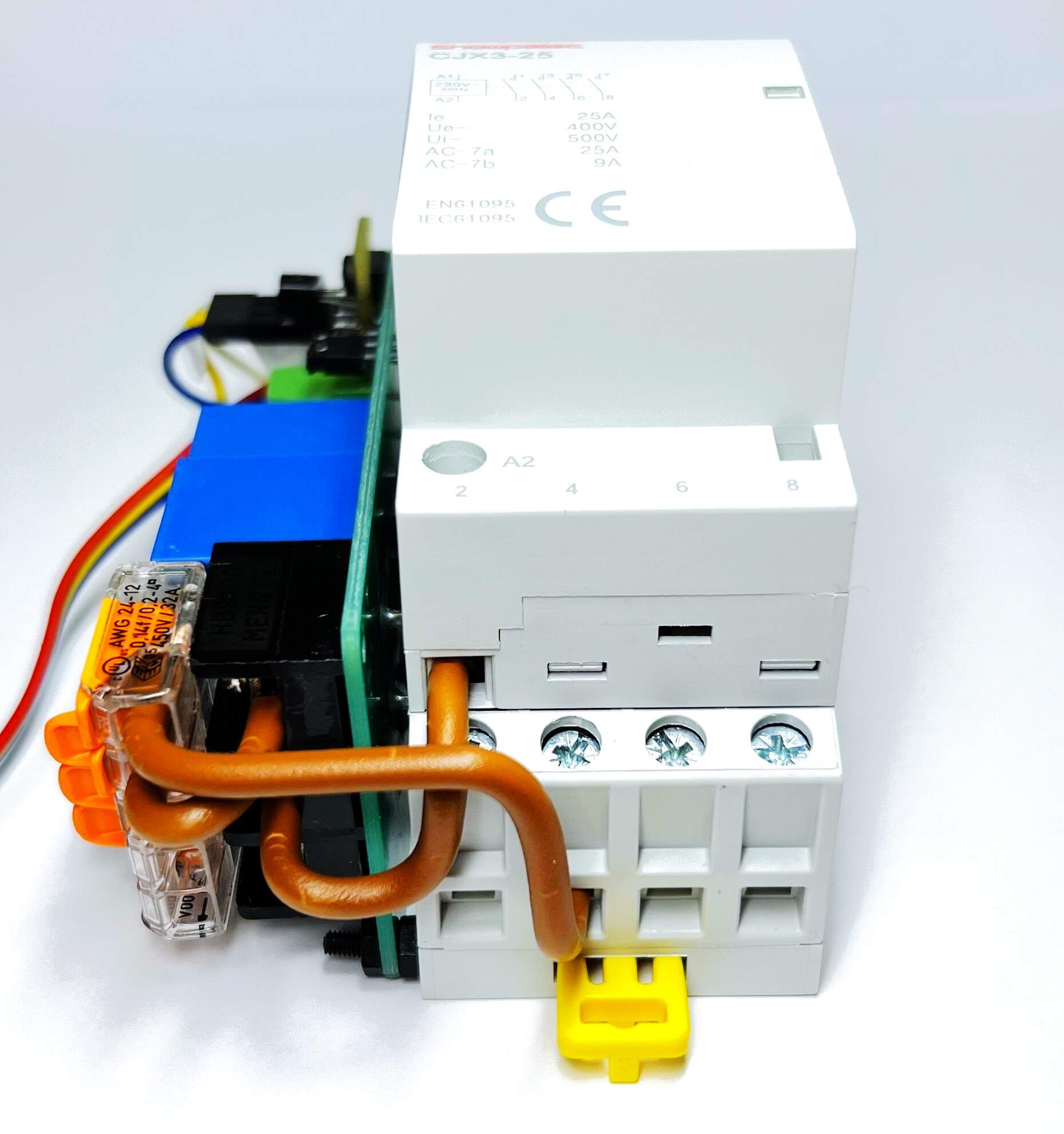
- Thread two M2.5 x 10mm screws through the holes in the bottom of the Contactor CJX3-25 230V/25A 4P and screw them tightly with M2.5 Hex nuts as you can see in the picture below.
- Place the relay module on the screws on the contactor and screw it with two M2.5 hex nuts as shown in the picture below.
- Use a brown wire with a cross-section of 2.5 mm² to connect the terminal of the relay module NO1 with the terminal of the contactor A2.
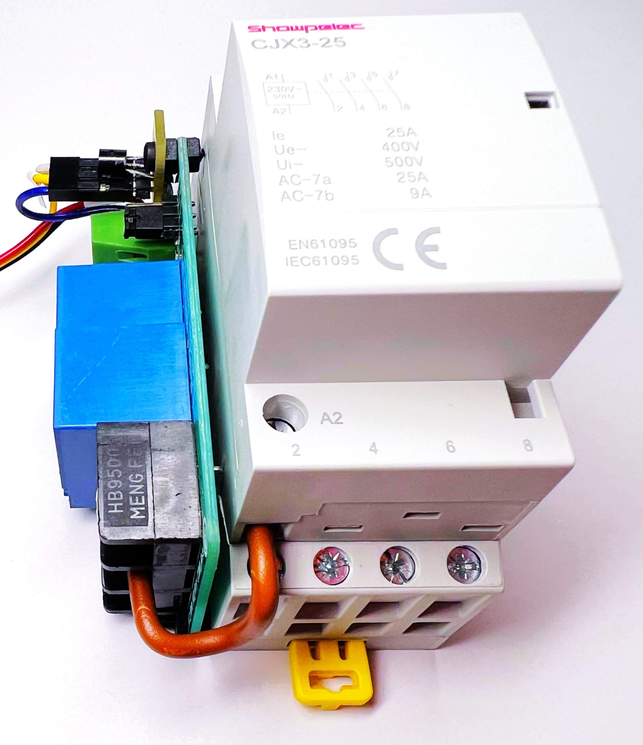
- Next, connect the terminal of the relay module COM1 with the terminal of the COMPACT Splicing Wago 221-415 connector with a brown wire with a cross-section of 2.5 mm².
- Finally, connect the COMPACT Splicing Wago 221-415 connector to terminal 4 on the contactor with a brown wire with a cross-section of 2.5 mm².
Box
Chassis
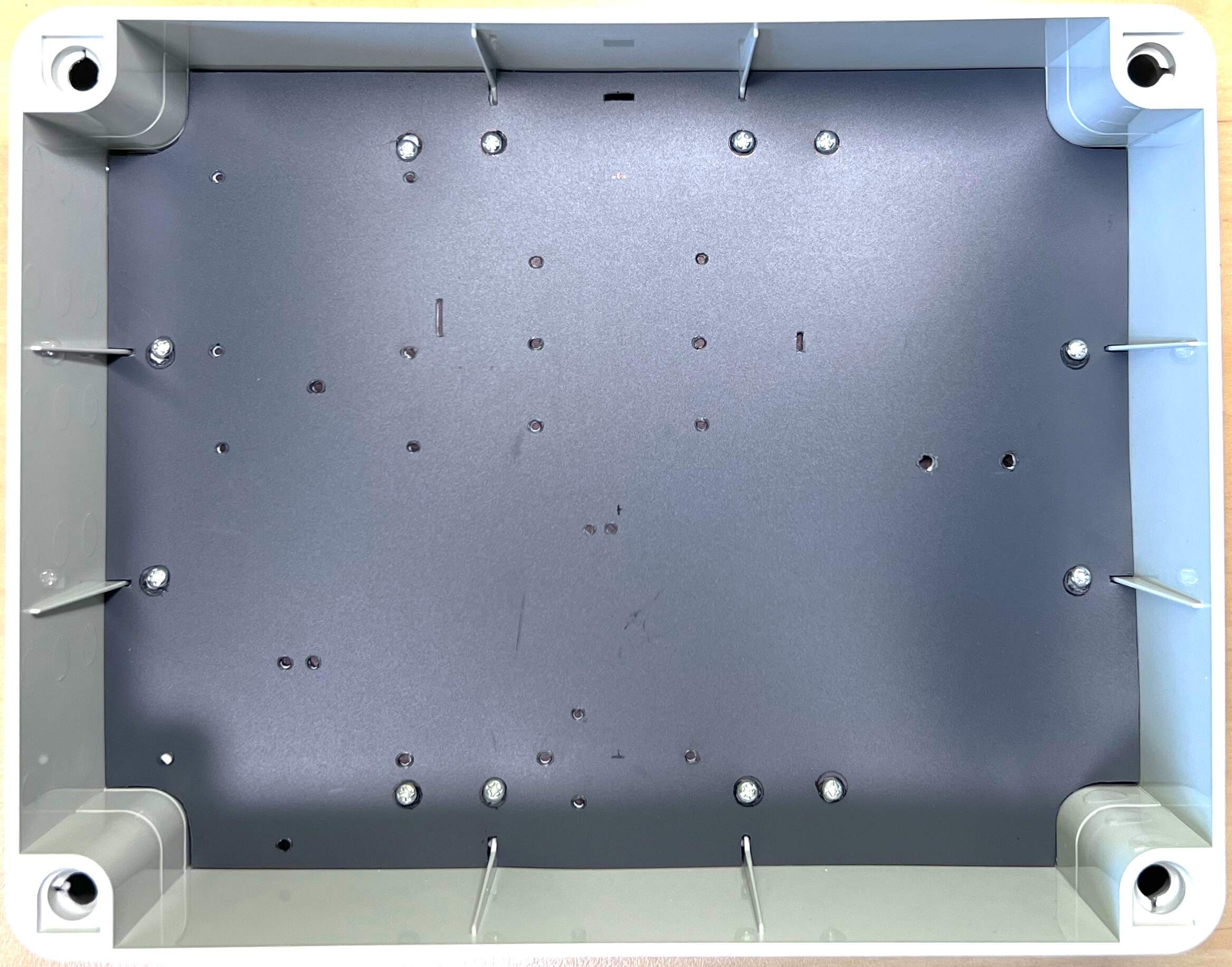
- Prepare the box Gewiss GW44208 – IP56 – 240x190x90.
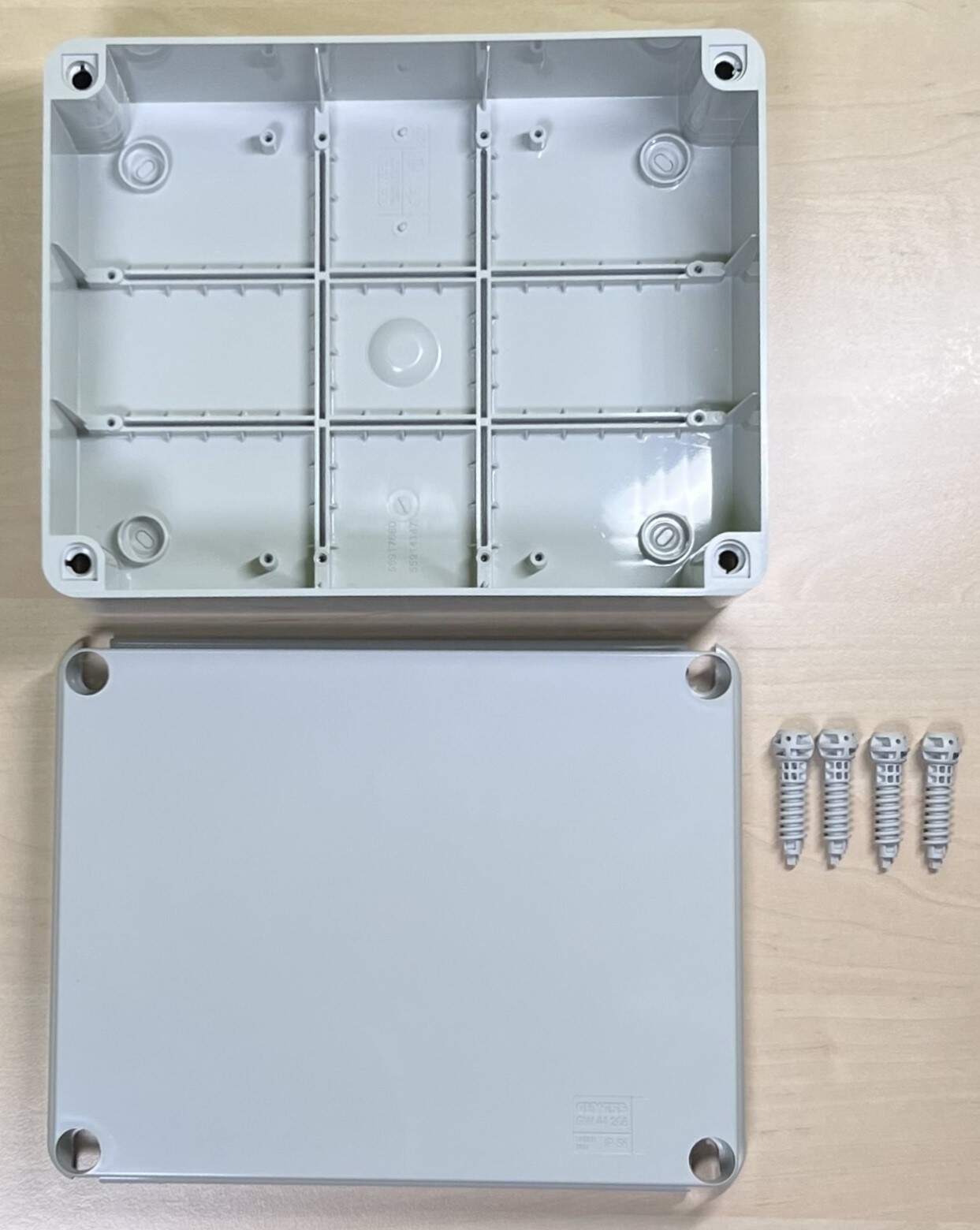
- Cut the plastic flat sheet plate 3 mm thick to cover all the mounting holes in the box as shown in the picture below.
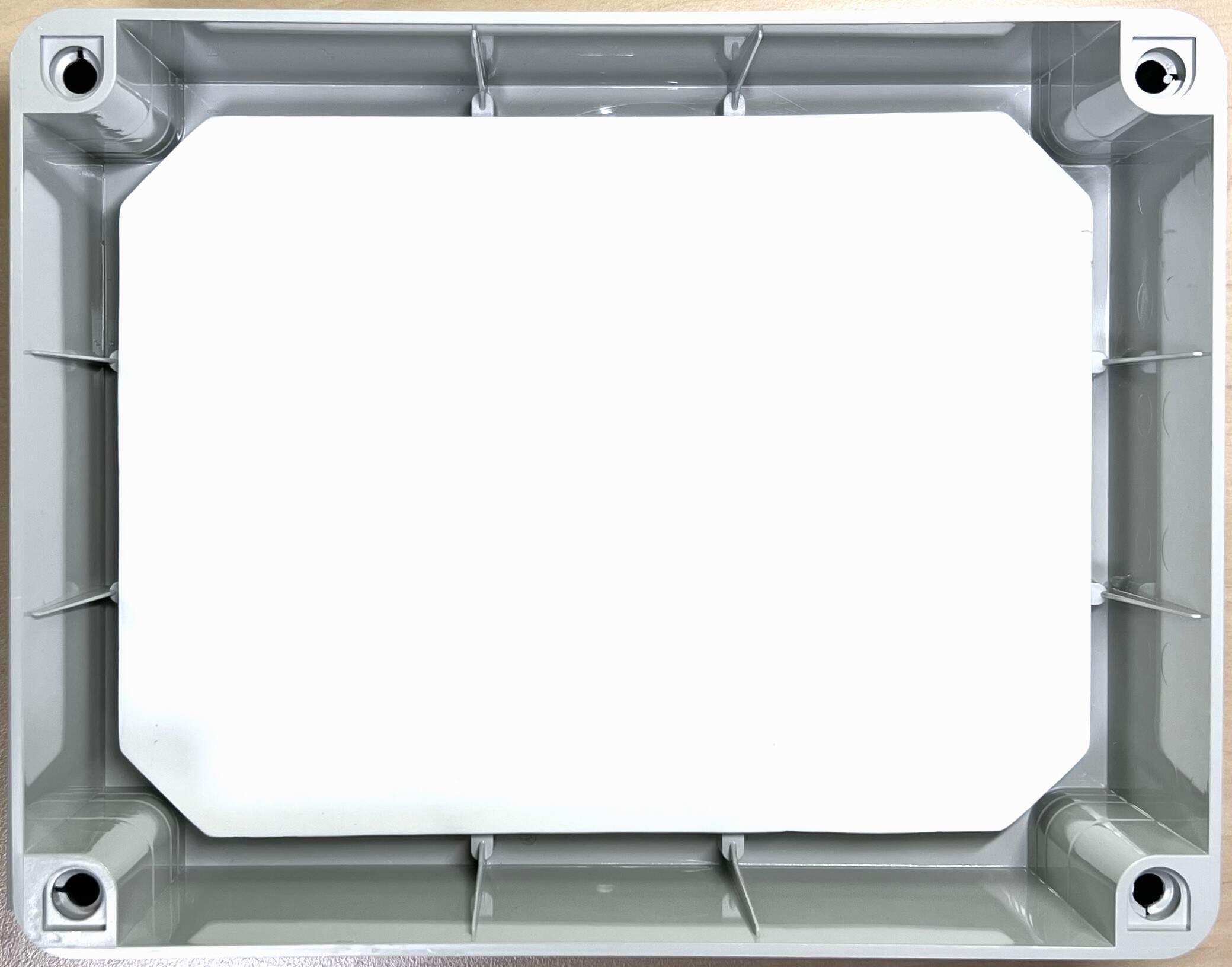
- Cut out the exact shape of the inside of the box from Modeling pad A3 and cut the holes according to the mounting holes in the box as shown in the picture below. Also drill mounting holes in the plastic flat sheet plate 3 mm thick.
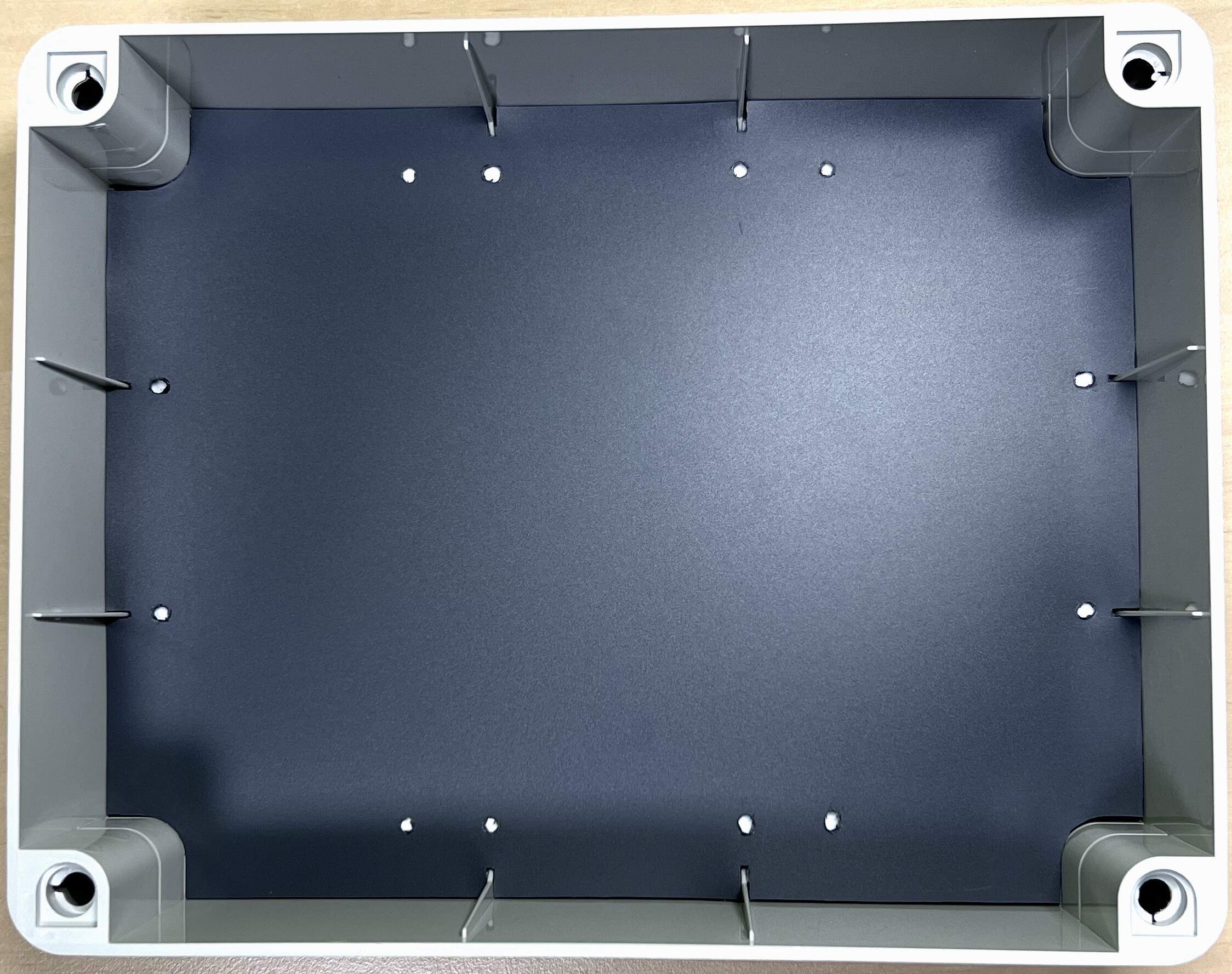
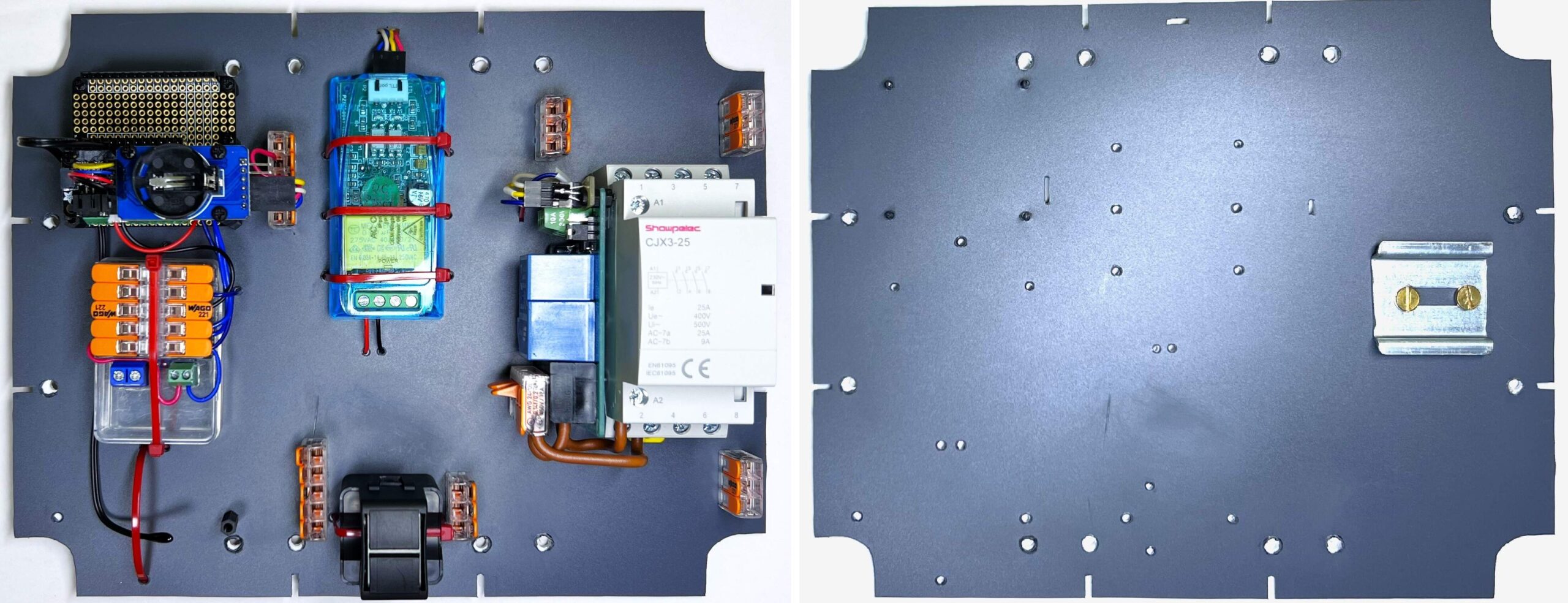
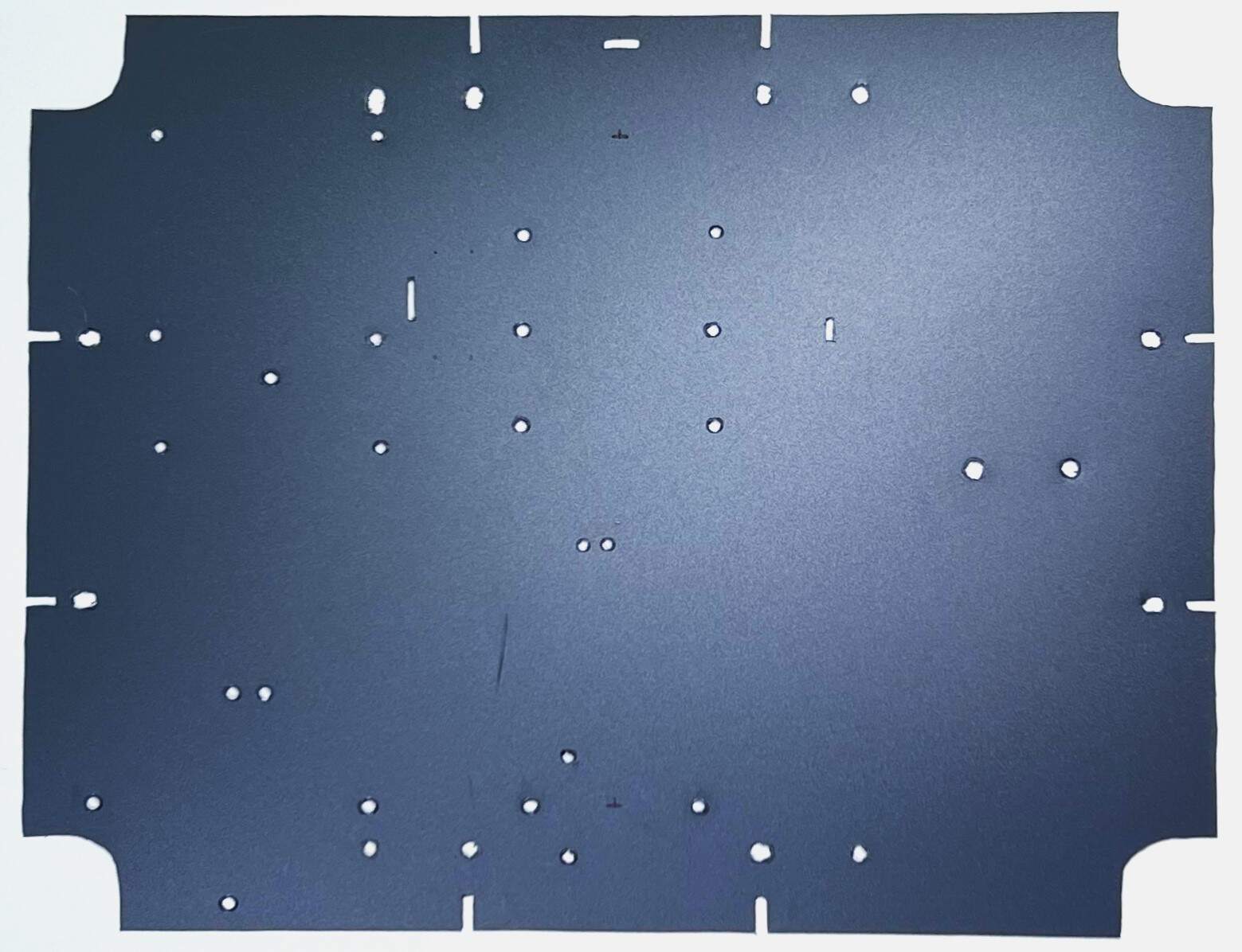
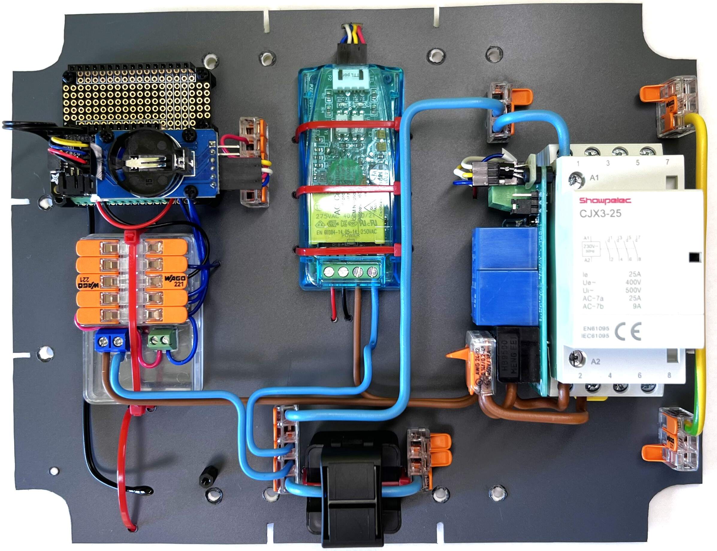
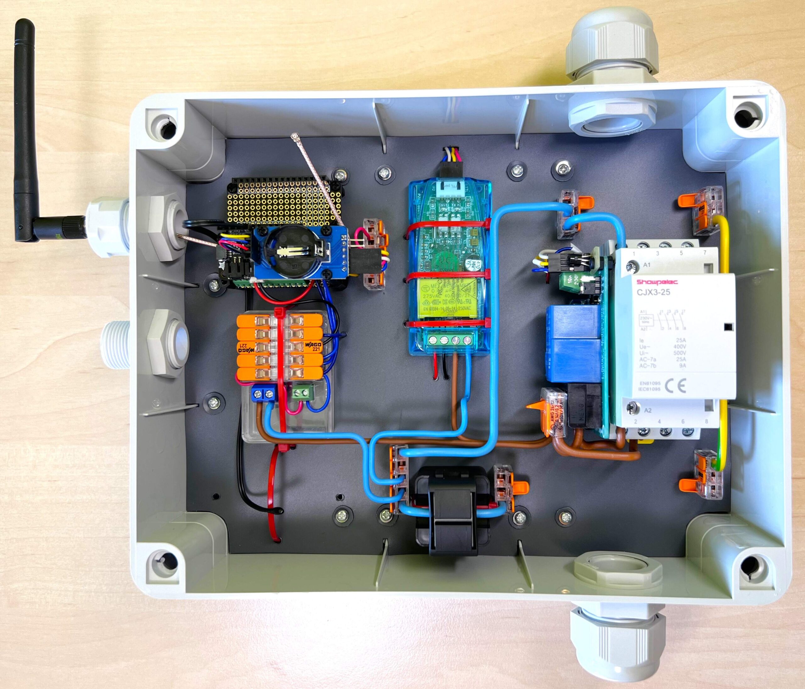
- Refer to the component layout in the following two images and create component mounting holes and cable holes in Modeling Pad A3 as shown in the third image.
- Lightly screw plastic flat sheet plate 3 mm thick and Modeling Pad A3 into the box using twelve screws 2.5 mm, length 10 mm.
- Draw the holes created in the Modeling Pad A3 using the Centropen OHP Permanent marker 2636 F on a plastic flat sheet plate 3 mm thick.
- Unscrew and take out the plastic flat sheet plate 3 mm thick and Modeling Pad A3 from the box.
- Drill the holes you sketched into the 3mm thick plastic flat plate.
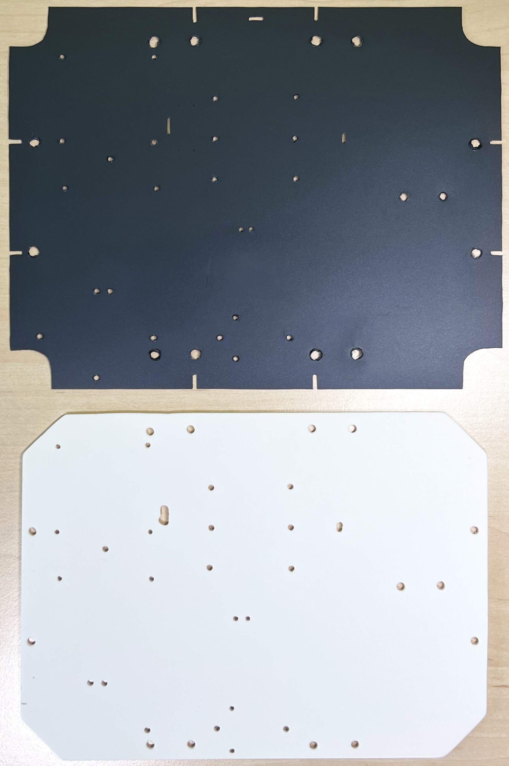
- Place the Modeling Pad A3 on top of a plastic flat sheet plate 3 mm thick and the chassis is ready.
Assembly of prepared parts
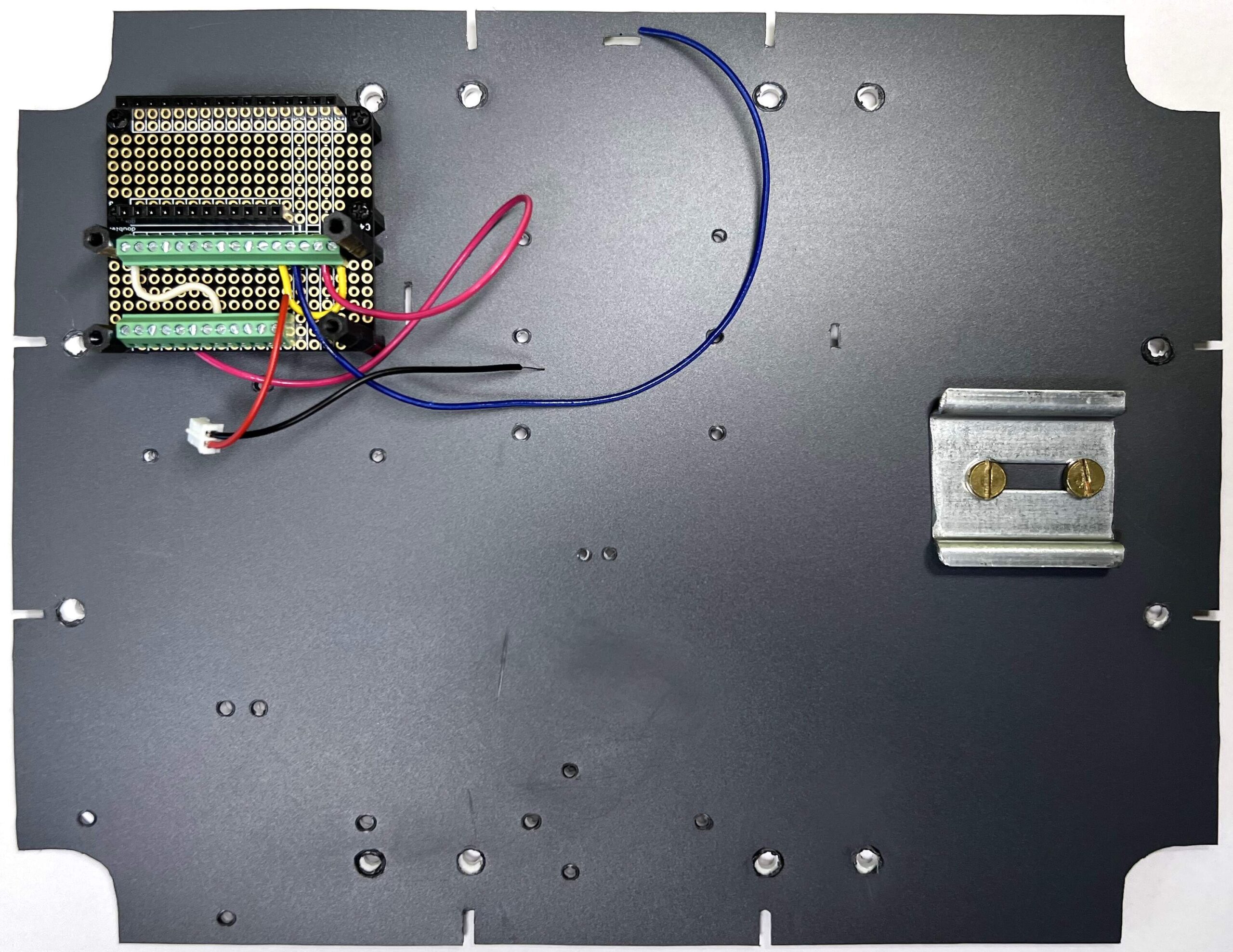
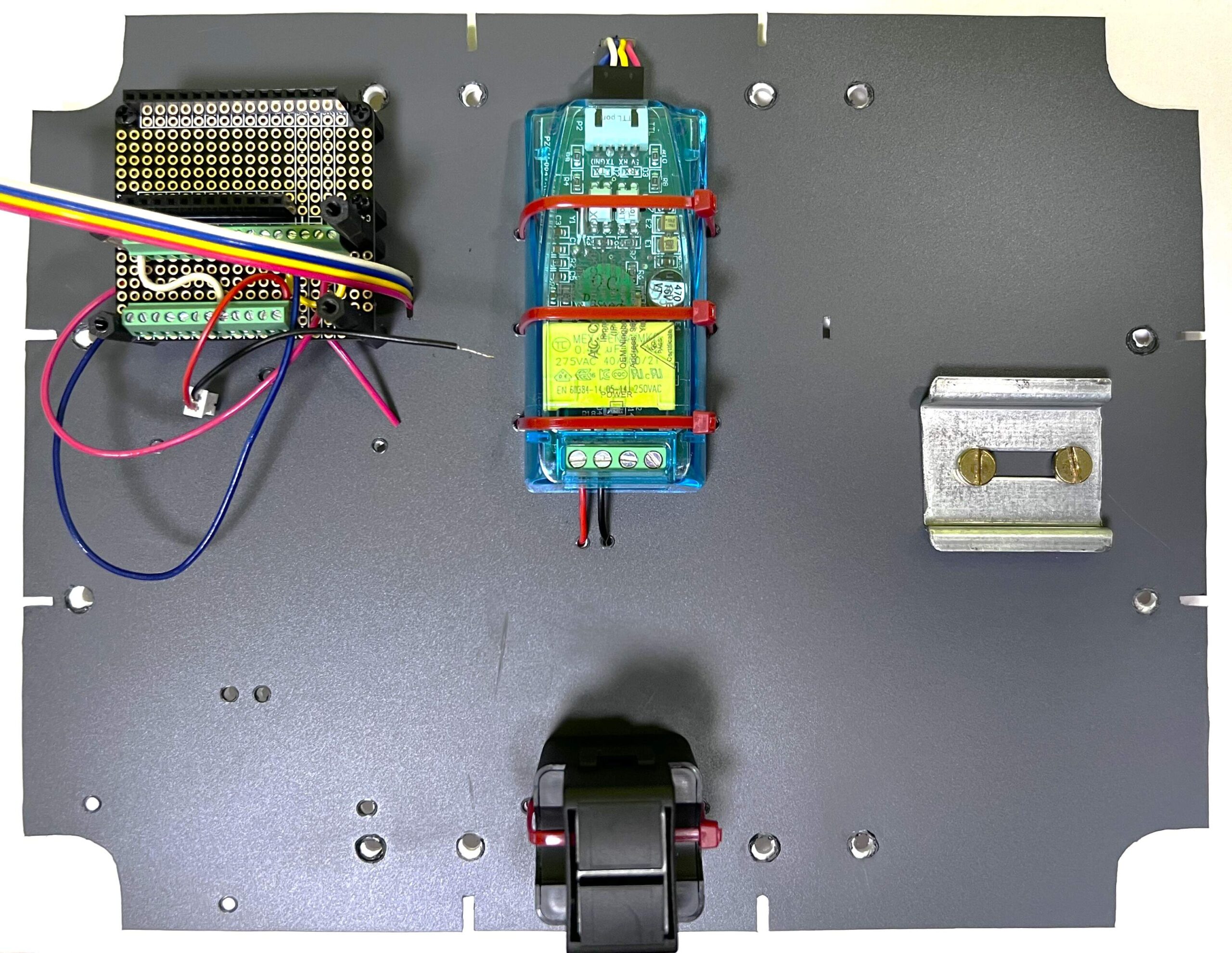
- Prepare the DIN rail 3.5 cm, 2x Bolt (short) and nut to the DIN rail, assembled FeatherWing Doubler (from the section “Cube” – First half) and 4x M2.5 x 10mm screw.
- Screw the DIN rail 3.5 cm using two bolts and nuts to the chassis on the right side as shown in the picture below.
- Screw the assembled FeatherWing Doubler (from the section “Cube” – First half) to the chassis using 4x M2.5 x 10mm screws as shown in the picture below.
- Thread the wires of the measuring coil through the holes in the chassis and then fasten the measuring coil with the help of two cable ties.
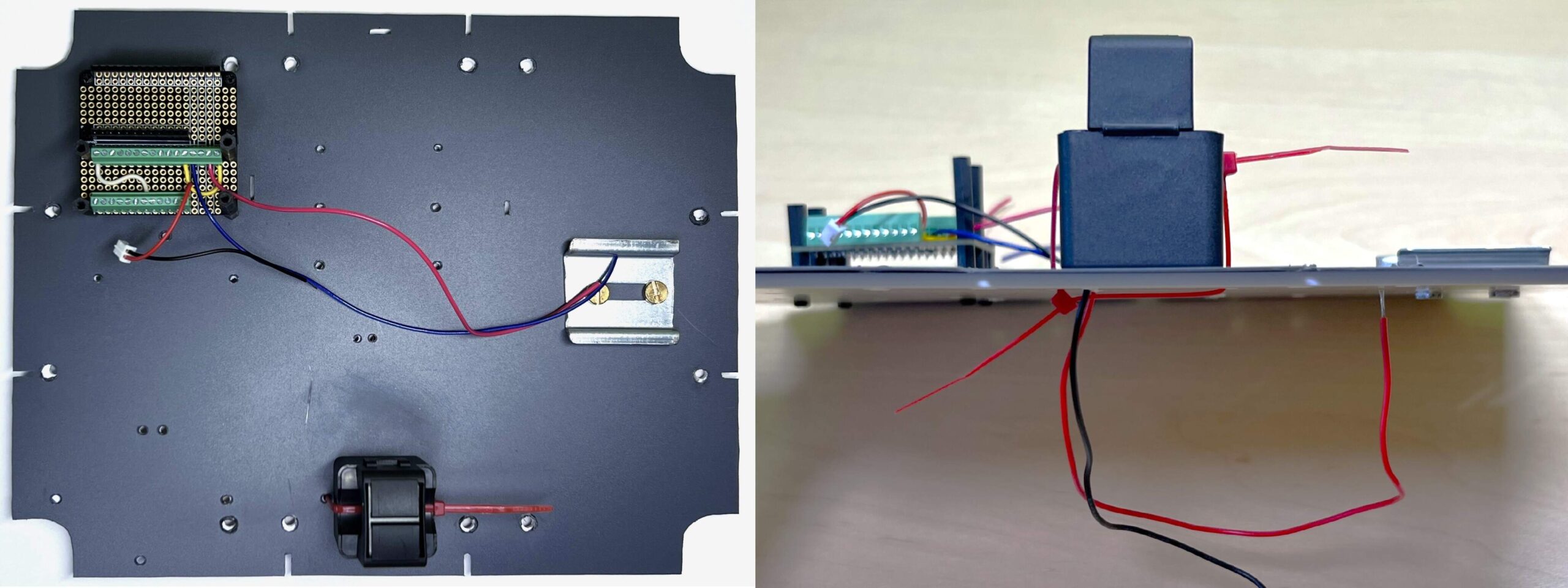
- Attach the PZEM-004T-100A-V3.0 measuring device to the chassis using six cable ties.
- Thread the wires of the measuring coil through the holes in the chassis and connect them to the PZEM as shown in the picture below.
- Connect the DuPont cable made in the “Electrical mains part – PZEM” section to the PZEM measuring device, thread it through the chassis and lead it out through the hole next to the “Cube”.
- Place the Contactor and relay block (created in the “Electrical mains part – Contactor and relay” section) on the 3.5 cm DIN rail.
- Thread the DuPont cable of this block through the chassis and divide it into individual wires under the chassis.
- Thread the yellow wire through the hole next to the “Cube” (where the cable from PZEM is threaded through).
- Thread the red wire under the “Cube” on the left side.
- Thread the blue wire under the “Cube” on the right side as shown in the picture.
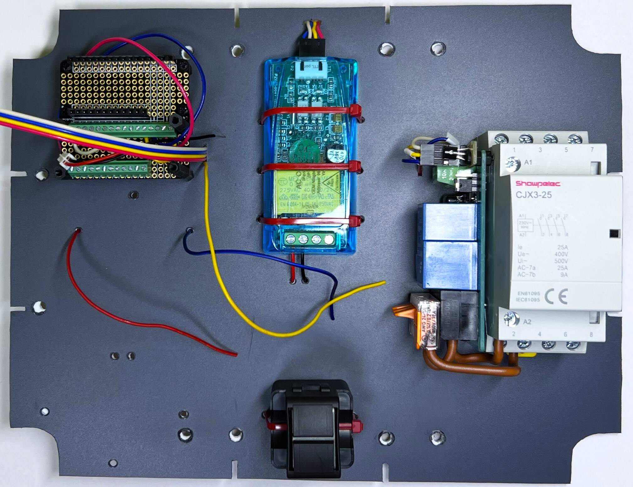
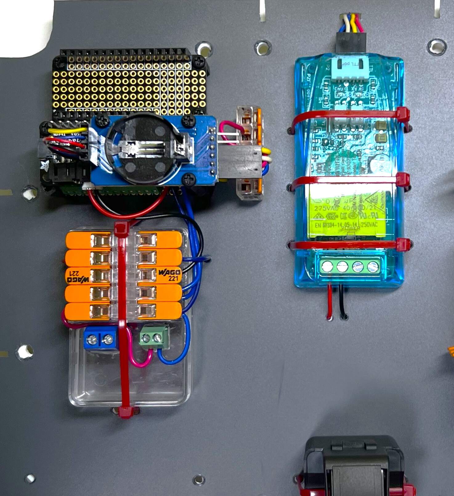
- Attach the 5V Power source (created in the “5V Power source” section) using three cable ties to the chassis as shown in the picture below.
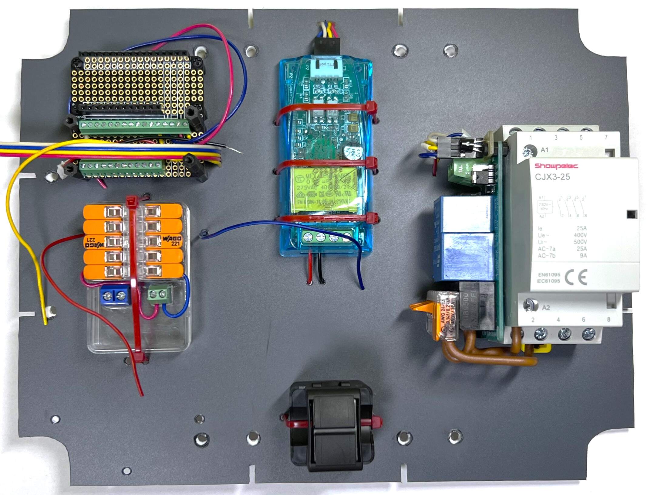
- Next to the “Cube” on the right side, glue the COMPACT Splicing Wago 221-415 connector as shown in the picture below.
- Connect the red wire of the DuPont cable from PZEM to the glued connector.
- Connect the white wire of the DuPont cable from PZEM to the pin RX0 on the FeatherWing Doubler.
- Connect the yellow wire of the DuPont cable from PZEM to the pin TX1 on the FeatherWing Doubler.
- Connect the yellow wire from the Contactor and relay block to the pin 12 on the FeatherWing Doubler.
- Connect the wire connected to the 3V pin on the FeatherWing Doubler (dark pink wire) to the glued connector.
- Connect the red wire from the Contactor and relay block to the left connector of the 5V Power source with 5 V.
- Connect a black wire, which has a JST connector on the other end, to the right connector of the 5V Power source with GND.
- Connect the blue wire from the Contactor and relay block to the right connector of the 5V Power source with GND.
- Connect the blue wire of the cable from PZEM to the right connector of the 5V Power source with GND.
- To the right connector of the 5V Power source with GND, connect the blue wire connected to the GND pin on the FeatherWing Doubler.
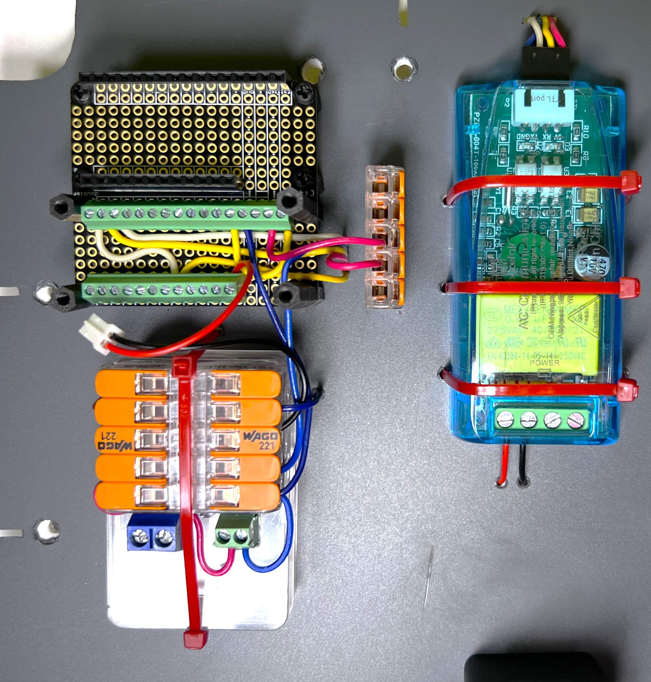
- Prepare the RTC and Adafruit LC709203F module and the DuPont cable (created in the “Cube” section – First half – RTC and Adafruit LC709203F).
- Use the yellow wire of the DuPont cable to connect the SCL pin on the RTC module to the SCL pin on the FeatherWing Doubler.
- Use the white wire of the DuPont cable to connect the SDA pin on the RTC module to the SDA pin on the FeatherWing Doubler.
- Connect the red wire of the DuPont cable to the VCC pin on the RTC module with the COMPACT Splicing Wago 221-415 connector next to the “Cube” on the right side as shown in the image below.
- Use the blue wire of the DuPont cable to connect the GND pin on the RTC module with the right connector of the 5V Power source with GND.
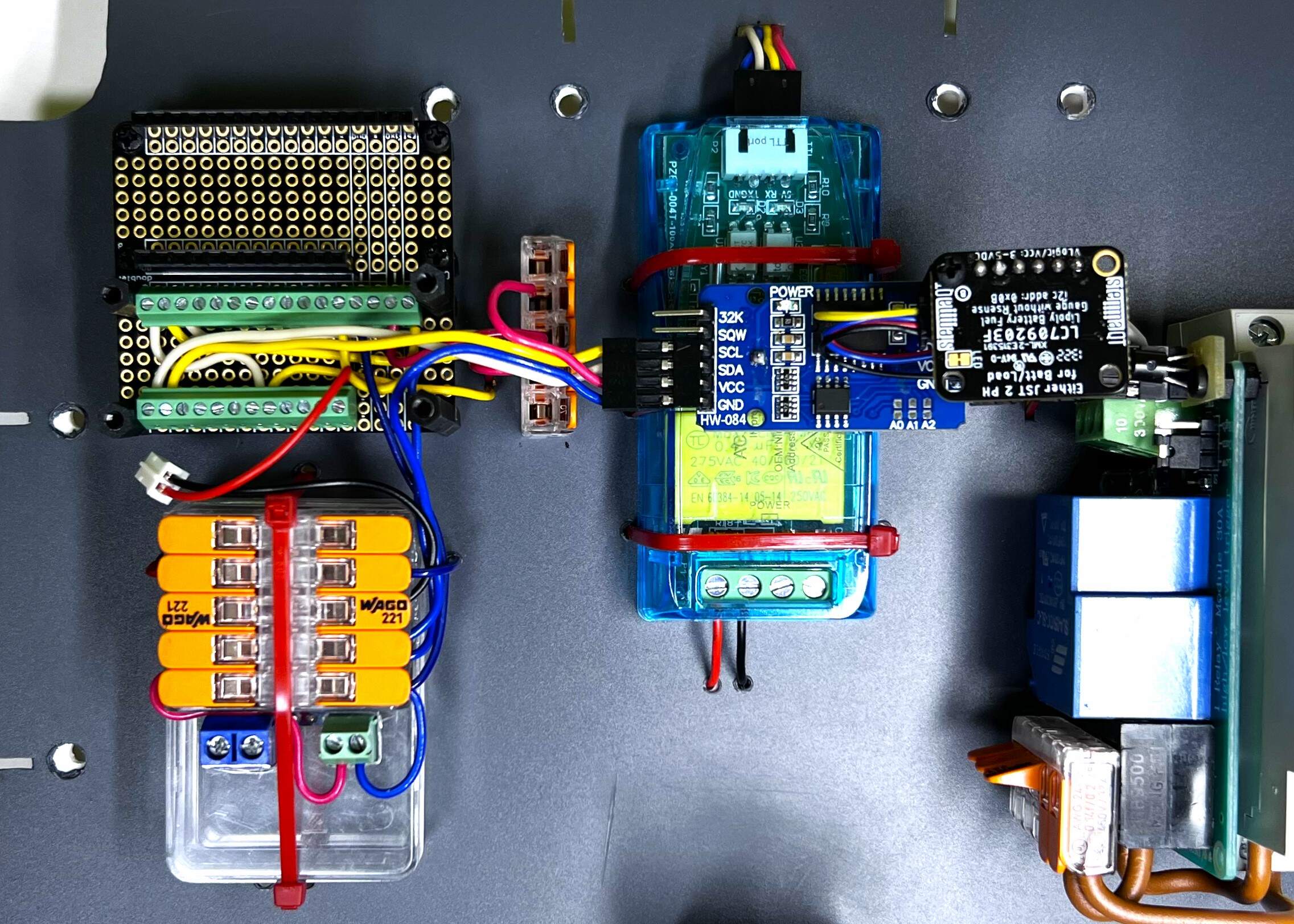
- Flip the connected RTC and Adafruit LC709203F block over and screw it to the FeatherWing Doubler using three M2.5 x 4mm Screws.
- Connect the JST connector to the JST socket on the Adafruit LC709203F.
- Attach the battery to the chassis using two cable ties.
- To the LC709203F module, connect the thermistor between the GND and Therm pins using a DuPont connector.
- Bring the thermistor to the battery.
- Glue the M2.5 hex nut from the bottom side of the chassis and screw the 12mm long M-F hex standoff into it from the top side of the chassis (on the right side of the battery).
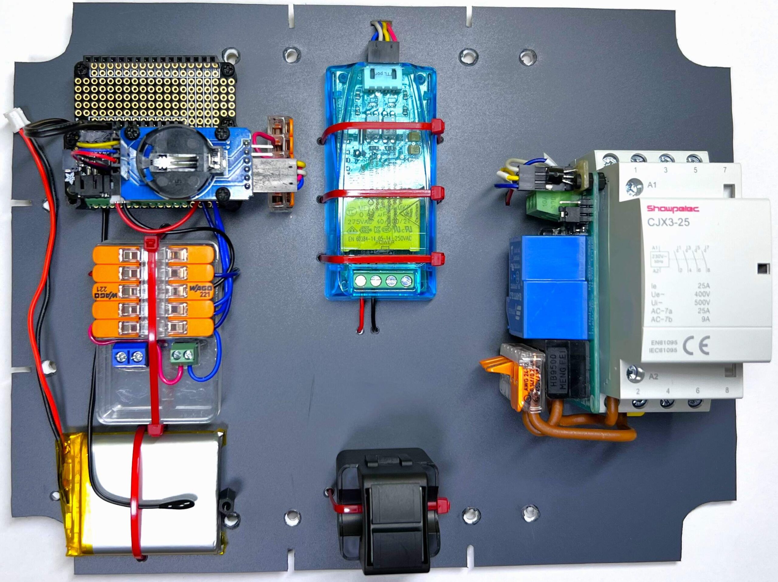
- Glue 4x COMPACT Splicing Connector Wago 221-413 and 1x COMPACT Splicing Connector Wago 221-415 to the chassis as shown in the picture below.
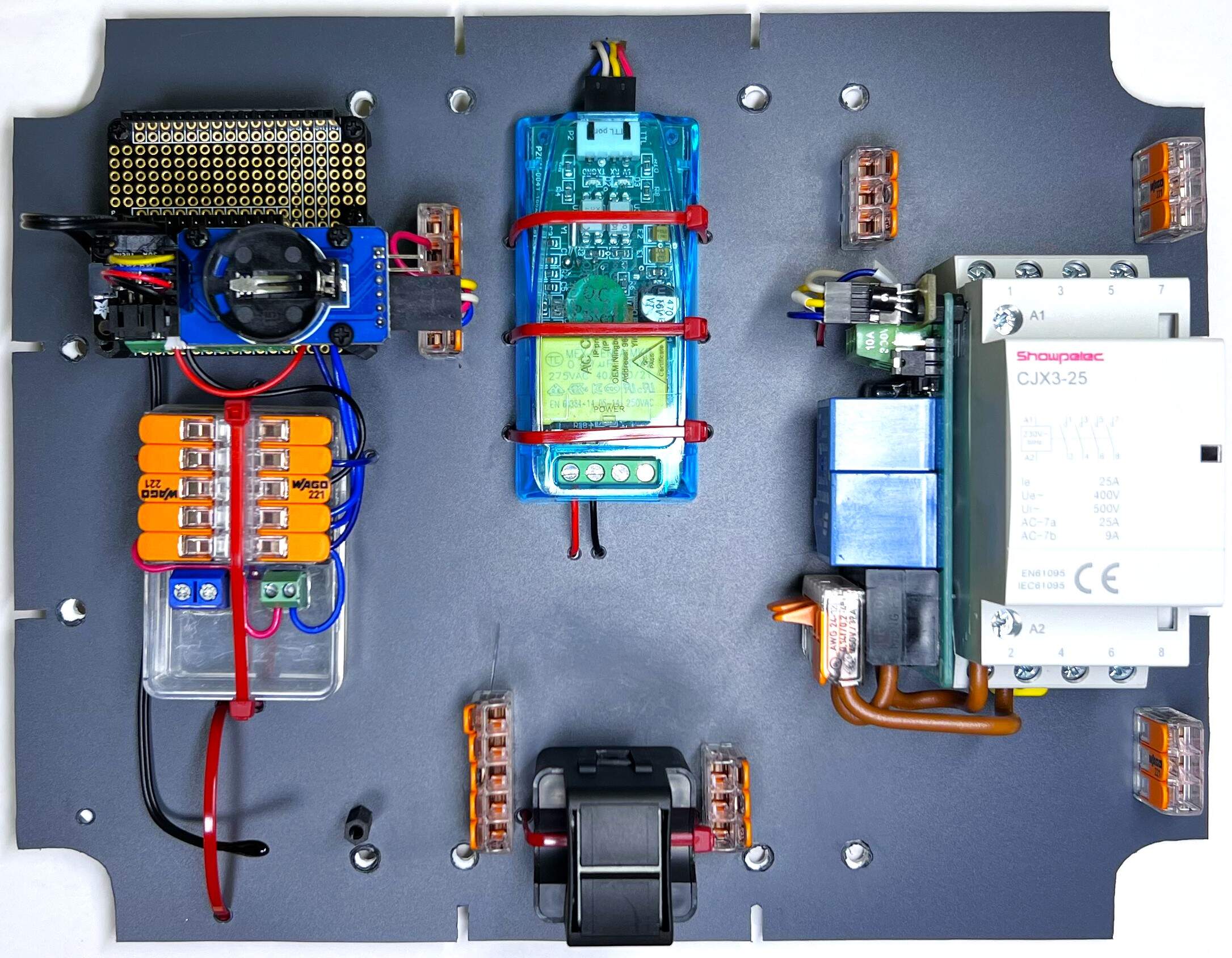
- Connect the live, neutral and ground wires to the individual components according to the picture below and the diagram at the top of the “Assembly” section.
- Drill holes for 2x cable gland Pg 13.5 and 2x cable gland M25x1.5 in the Gewiss GW44208 box.
- Insert the chassis into the box and screw it to the mounting holes of the box using 12x Screw 2.5 mm, length 10 mm.
- Screw cable gland Pg 13.5 with antenna, cable gland Pg 13.5 for light intensity sensor BH1750 and 2x cable gland M25x1.5 for input wires and output wires for switched equipment into the drilled holes in the box.
- Thread the antenna cable through the “Cube”.
- Pass the light intensity sensor cable through the cable gland Pg 13.5 into the box, secure it with a cable tie and connect the STEMMA QT connector to the STEMMA QT input on the LC709203F module.
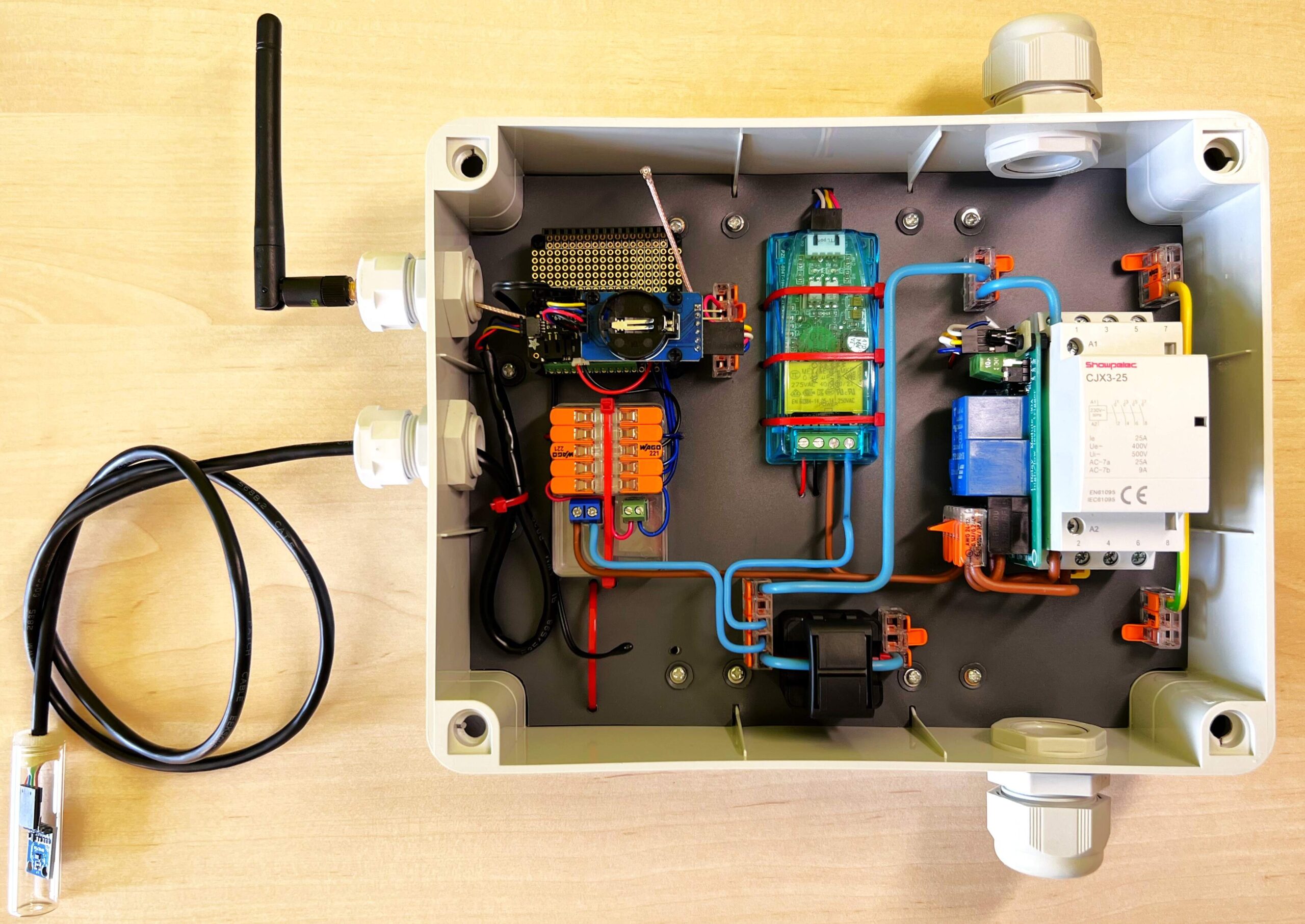
- Connect the antenna cable to the Adafruit Feather M0 board.
- Plug the Adafruit Feather M0 board into the FeatherWing Doubler.
- Screw the Adafruit Feather M0 board using 4x M2.5 x 4mm Screws.
- Connect the cable with the Micro-USB B connector to the 5V Power source with the correct polarity.
- Connect the Micro-USB B connector to the Adafruit Feather M0.
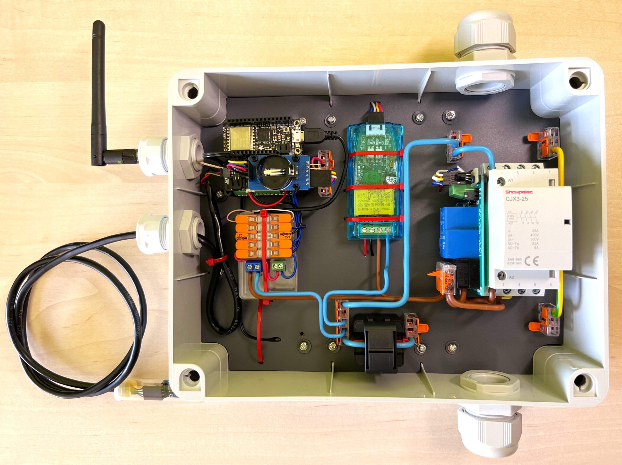
- Connect the battery to the LC709203F module using the JST connector.
- Finally, connect the assembled multifunctional switching device to the mains.
Arduino IDE setup
Arduino IDE and board setup
- Download Arduino IDE.
- Run Arduino IDE.
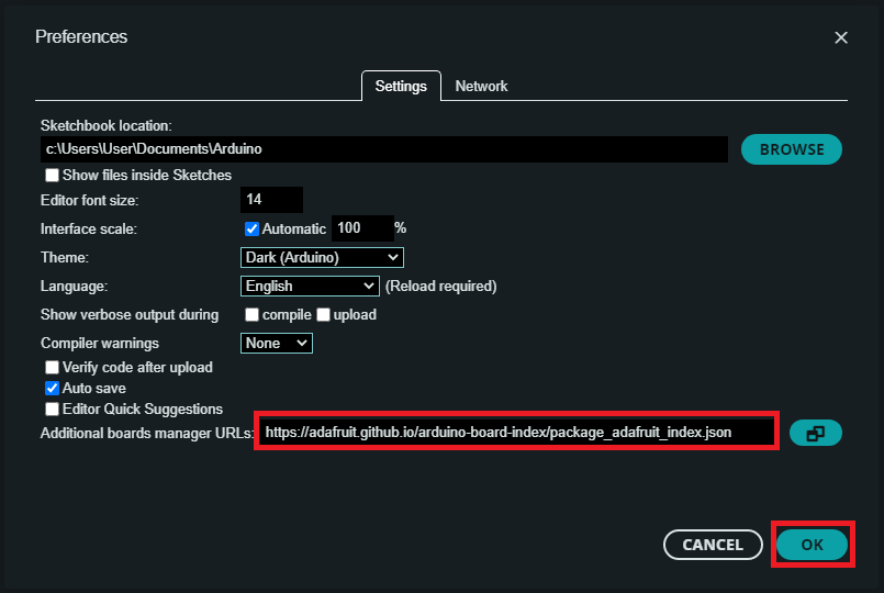
- In the Arduino IDE File -> Preferences copy and paste the link below into the Additional Boards Manager URLs.
https://adafruit.github.io/arduino-board-index/package_adafruit_index.json - Click OK.
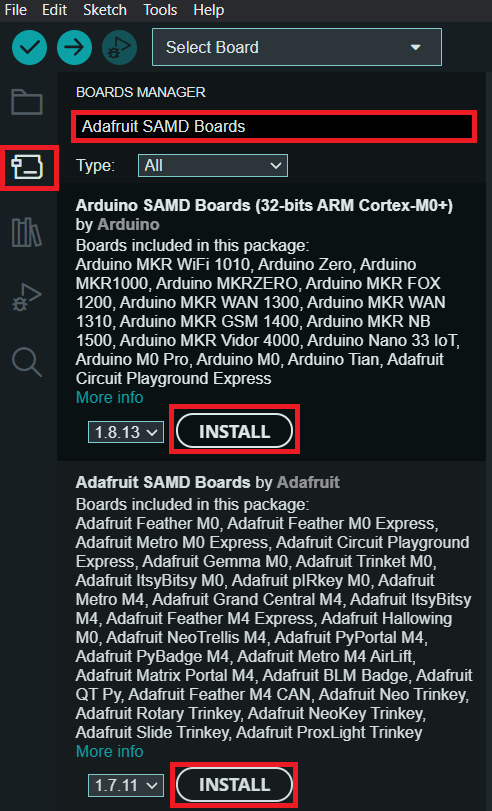
- Install the Adafruit boards via Boards Manager -> search Arduino SAMD Boards -> Install.
- Install the Adafruit boards via Boards Manager -> search Adafruit SAMD Boards -> Install.
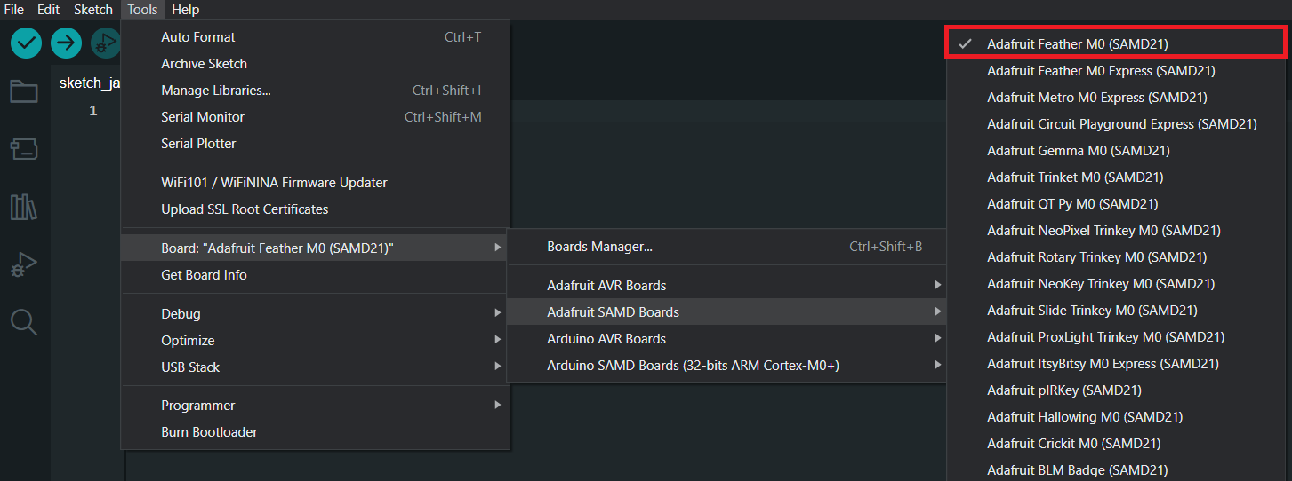
- You should see in Tools -> Board -> Adafruit SAMD the Adafruit Feather M0.
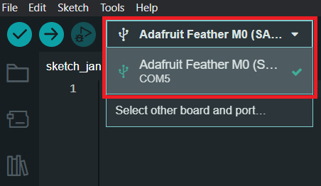
- Connect the Adafruit Feather M0 using micro USB cable to your computer.
- Choose the appropriate COM port which is used for communication with Adafruit.
Arduino IDE – Included Libraries
- In the Arduino IDE Library Manager search and install it with all dependencies:
- Adafruit LC709203F by Adafruit
- hp_BH1750 by Stefan Armborst
- RTClib by Adafruit
- Timezone by Jack Christensen
- ArduinoJson by Benoit Blanchon
- Adafruit Fram I2C by Adafruit
- Download as ZIP this libraries:
- PZEM-004T-V30-SAMD21 by zygisjas.
- CayenneLPP_Arduino by OndrejKnebl – added the datatype to original code from Electronic Cats
- EEPROM_additional_functions by OndrejKnebl
- SunriseSunset by OndrejKnebl
- In the Arduino IDE Sketch -> Include Library -> Add .ZIP Library… choose downloaded ZIP.
- Add all downloaded ZIP libraries.
MCCI LoRaWAN LMIC library setup – Over The Air Activation (OTAA), Device class A
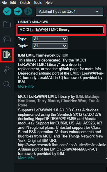
- In the Arduino IDE Library Manager search MCCI LoRaWAN LMIC library by Terry Moore and install it.
- On Windows open lmic_project_config.h located in \Documents\Arduino\libraries\MCCI_LoRaWAN_LMIC_library\project_config\
- Change project definitions to definitions listed bellow and save it.
// project-specific definitions
#define CFG_eu868 1                  // for Europe (change it based on your location)
#define CFG_sx1276_radio 1
#define DISABLE_PING 1               // Device Class B disabled
#define DISABLE_BEACONS 1            // Device Class B disabled
#define LMIC_ENABLE_DeviceTimeReq 1  // TTS Network Time
The Things Stack setup
Add Feather M0 into The Things Stack
- Create an account on The Things Network if you don’t have one.
- Login on The Things Network.
- Click on your username and choose Console.
- Select a network cluster.
Add application
- Go to applications.
- Click on button + Create application.
- Write something into Application ID.
- Click on button Create application.
Add end device
- In your application click on button + Register end device.
- Input Method – Choose Enter end device specifics manually.
- Frequency plan – Europe 863-870 MHz (SF9 for RX2 – recommended)
- LoRaWAN version – LoRaWAN Specification 1.0.3
- Click on Show advanced activation, LoRaWAN class and cluster settings
- Activation mode – Over the air activation (OTAA)
- Additional LoRaWAN class capabilities – None (class A only)
- Deselect – Use network’s default MAC settings
- Rx2 data rate = 3
- Rx2 frequency = 869,525 MHz
- JoinEUI – 0000000000000000
- Click on Confirm.
- DevEUI – Generate
- AppKey – Generate
- End device ID – here you can name your device
- After registration – View registered end device
- Click on button Register end device
- Click on General settings
- Network layer – Expand
- Click on Advanced MAC settings
- Desired Rx1 delay = 1
- Rx1 data rate offset = 0
- Add Frequency = 868100000
- Add Frequency = 868300000
- Add Frequency = 868500000
- Add Frequency = 867100000
- Add Frequency = 867300000
- Add Frequency = 867500000
- Add Frequency = 867700000
- Add Frequency = 867900000
- Adaptive data rate (ADR) – Disabled
- Click on button Save changes
CayenneLPP formatter – Additional data types and Original LPPv1 data types
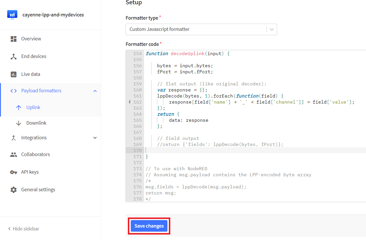
- In TTS -> Applications -> YourAppName -> Payload formatters -> Uplink change Formatter type to Custom Javascript formatter.
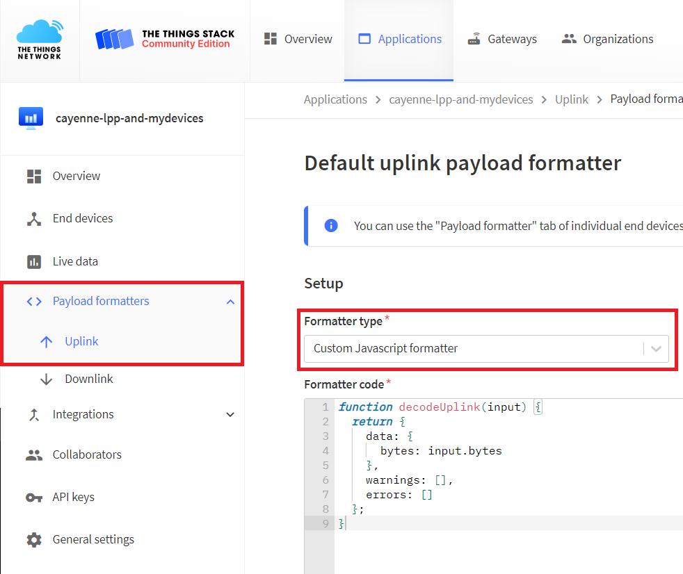
- To the Formatter code field copy and paste Cayenne LPP Decoder.
- Save changes.
Program
- To your Arduino IDE copy and paste program for Multifunctional Switching Device.
- In program replace APPEUI, DEVEUI and APPKEY with keys in TTS. Keys are in TTS -> Applications -> YourAppName -> YourEndDeviceName -> Overview -> Activation information.
- Furthermore, the selected password must be entered in the myPassword variable in the program.
- In the program, in the section marked “Here change your default settings”, it is possible to define the time correction, how often the time should be requested from the TTS network, the SF value and other settings, which are commented in detail in the program.
- Connect Adafruit Feather M0 using micro USB cable to your computer.
- Choose the appropriate COM port which is used for communication with Adafruit.
- In Arduino IDE click on Upload button to upload program to your Adafruit Feather M0.
- In TTS -> Applications -> YourAppName -> YourEndDeviceName -> Live data you should every 1 minute (Default value) see decoded uplink data from Multifunctional Switching Device.
Program description
Based on the implemented working modes, the MSD can switch the connected device according to the light intensity or the set switching times. Furthermore, according to the light intensity at the selected times or according to the sunrise and sunset in the place defined by the coordinates. The MSD can also be always on or off.
The program sends measured data from the PZEM measuring device and the BH1750, LC709203F and RTC modules to the LoRaWAN network. Furthermore, information about contactor states, the currently set MSD configuration, errors and sunrise and sunset times are sent to the network. All data listed is encoded and sent in CayenneLPP format with added data types. Additionally, a custom data type for time was added to the CayenneLPP library, as the type defined in the original unix time library was unnecessarily large at 4 bytes compared to the newly defined 3 byte type. This new type is large enough to send time to and from the MSD.
The program further implements data processing from received downlinks. The used MCCI LoRaWAN LMIC library has implemented in its examples of use only the statement of the information that the downlink was received and the statement of how many bytes of the payload were received. The code for listing and decoding received data has been implemented. The CayenneLPP format was also chosen for the payload received in downlinks, which is decoded on the device using the aforementioned CayenneLPP library.
Device communication was divided using FPort numbers so that 1 is used for sending measured data in uplinks and 2 for both uplinks and downlinks with configuration data.
In the case of receiving a downlink with an FPort number other than 2, the received payload is not processed. The decoded payload must also contain the correct numeric password, otherwise the received MSD settings will not be applied. If valid settings are sent in the appropriate channels and data types according to the CayenneLPP that the code implements, the ranges of received setting values are checked. When the data with the settings are within the implemented ranges, these settings are applied, stored in the EEPROM memory, and an uplink is sent from the MSD with information about the new configuration. If settings with values outside the range are sent, these settings are not applied and an uplink is sent from the MSD with information about the current configuration and the error of the specified setting.
Using downlinks, it is possible to set many MSD functions at once. For example, there is an option to set in which intervals the device will send the measured data and from how many samples this data will be averaged. Furthermore, it is possible to change the working mode of the MSD with downlinks, for example from switching according to light intensity to switching according to set times. It is also possible to choose which data will be sent in uplinks.
MSD obtains the date and time from the TTS network and stores them in the RTC module. The data with the set configuration is stored in the EEPROM in case of restarting the Feather, so that it is not necessary to perform the MSD settings again using downlinks.
All data that is sent in the uplinks is also listed with CayenneLPP encoding in tables. The data that is received in the downlinks is also shown with decoding in the tables. How the data is stored in the EEPROM is shown in table.
More information about some parts of the program
- More information about Cayenne LPP can be found here: https://lora.vsb.cz/index.php/cayenne-lpp/
- More information about TTS Network Time can be found here: https://lora.vsb.cz/index.php/tts-network-time/
- More information about Downlink reception and Cayenne LPP decoding can be found here: https://lora.vsb.cz/index.php/downlink-reception-and-cayenne-lpp-decoding/
Telegraf, InfluxDB & Grafana
For data storage and visualization, we use an open-source time series database InfluxDB and an open-source analytical and interactive visualization web application Grafana. Data from The Things Stack is sent via MQTT to the MQTT consumer Telegraf, which then stores the data in the InfluxDB database.
- Install the TIG following the instructions in this tutorial: https://lora.vsb.cz/index.php/telegraf-influxdb-grafana/
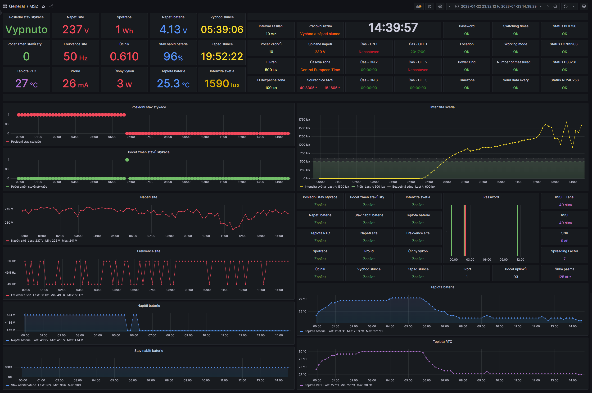
Grafana dashboard setup
- Add the required panels according to the procedure given in the tutorial (in the section “Grafana dashboard setup”) and enter queries using the Query table.
- To find out the set bits, for example, from the value in uplink_message_decoded_payload_digital_in_150, it is necessary to write the query manually.
- In the settings of the newly added blank panel, press the pencil symbol and put the query with your topic in the field.
- An example of creating a query to determine if a Switching times error has occurred is shown below and uses a bitwise AND:
SELECT last("uplink_message_decoded_payload_digital_in_150"::integer) & 16 FROM "tts" WHERE ("topic" = 'v3/msd@ttn/devices/msd-1/up') AND $timeFilter GROUP BY time($__interval) fill(null) - Use the same methods mentioned for all required panels.
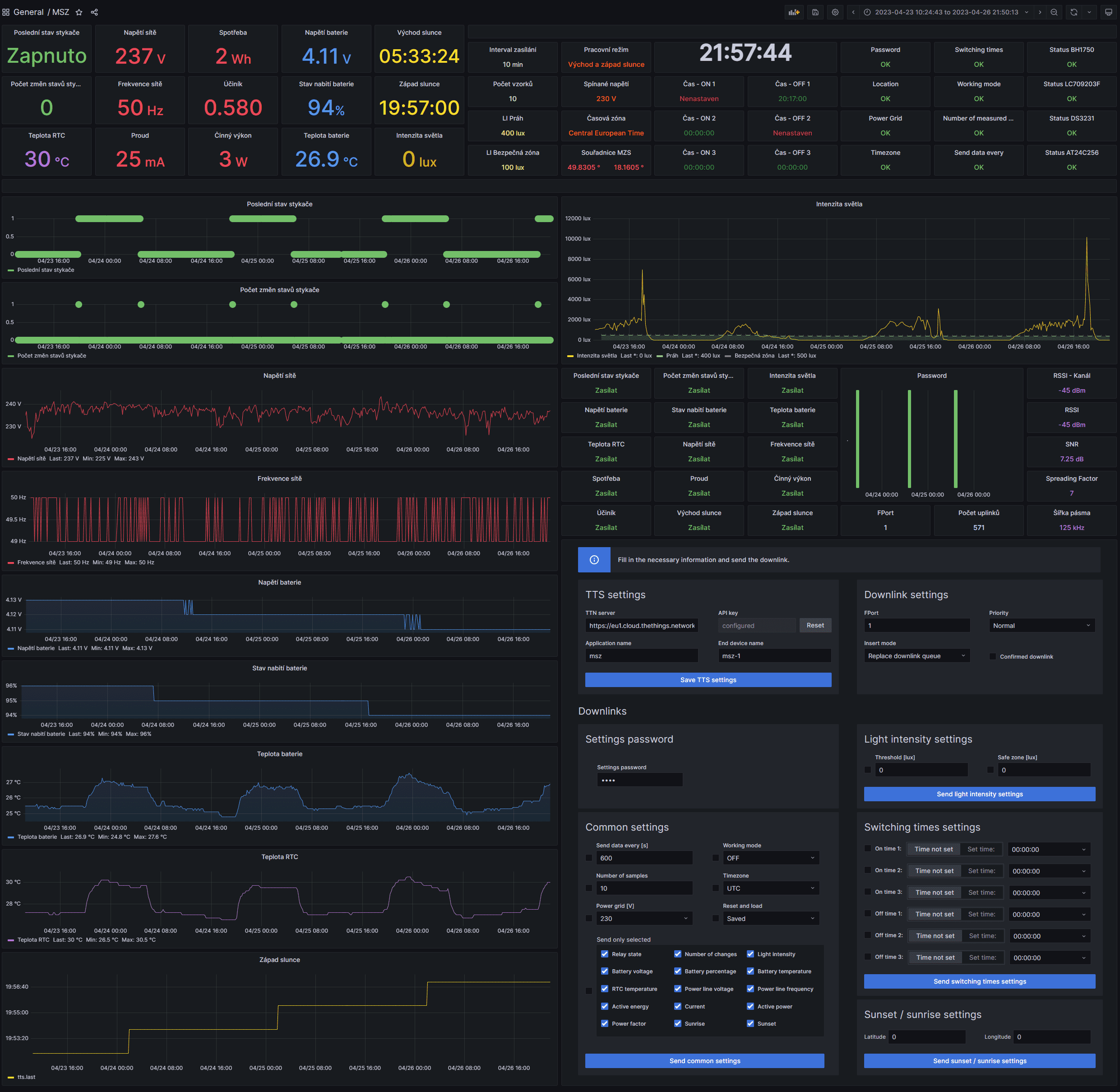
- For example, your Dashboard might look like this:
MSD control via downlinks
The following section describes the ways in which MSD settings can be changed using settings sent in downlinks from the TTS network.
First, you will need to generate an API key in TTS in your application, following the procedure below. You will need this generated API key for all downlink solutions below.
The Things Stack – API key
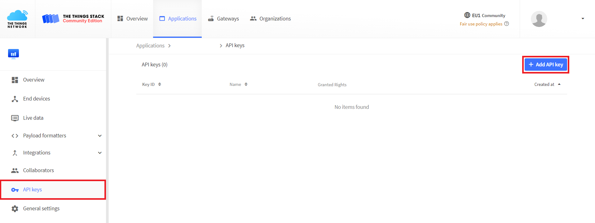
- In TTS -> Applications -> YourAppName -> API keys click button +Add API key.
- Write something in the Name.
- Select Grant individual rights.
- Check Write downlink application traffic.
- Click on button Create API key.
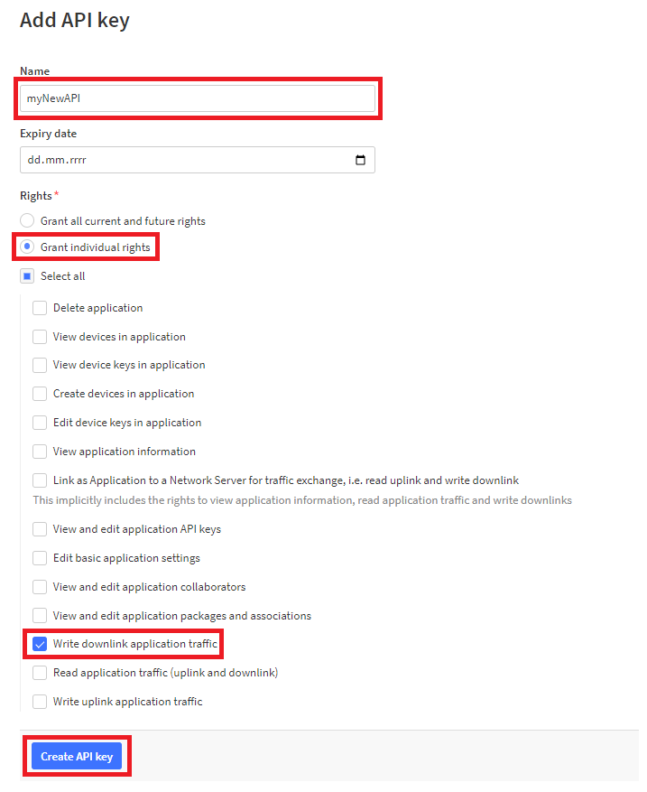
- Click the Copy to Clipboard button and save the key somewhere safe for later use.
Controling device with downlinks from python script or program
One option for setting MSD via downlinks is using a python script or program. The program mentioned is a graphical user interface that has a script code base in it. In addition, the program implements checks of entered settings and ranges. Cayenne LPP automatic encoding is implemented for both script and program. Encoded data is sent to TTS using the POST method.
Requirements
Sending downlinks via TTS using a Multiswitch Python script
The Multiswitch Python script contains the implementation of all possible MSD settings and all setting options have been commented in detail in the code. This script does not do any MSD checking of settings and ranges and may send settings that MSD does not implement. This script is a modified script originally developed for the Sending downlinks via TTS using a Python script tutorial.
We recommend going through this tutorial where you will learn how to Send downlinks via TTS using a Python script .
- The script for MSD can be found here: Multiswitch Python script
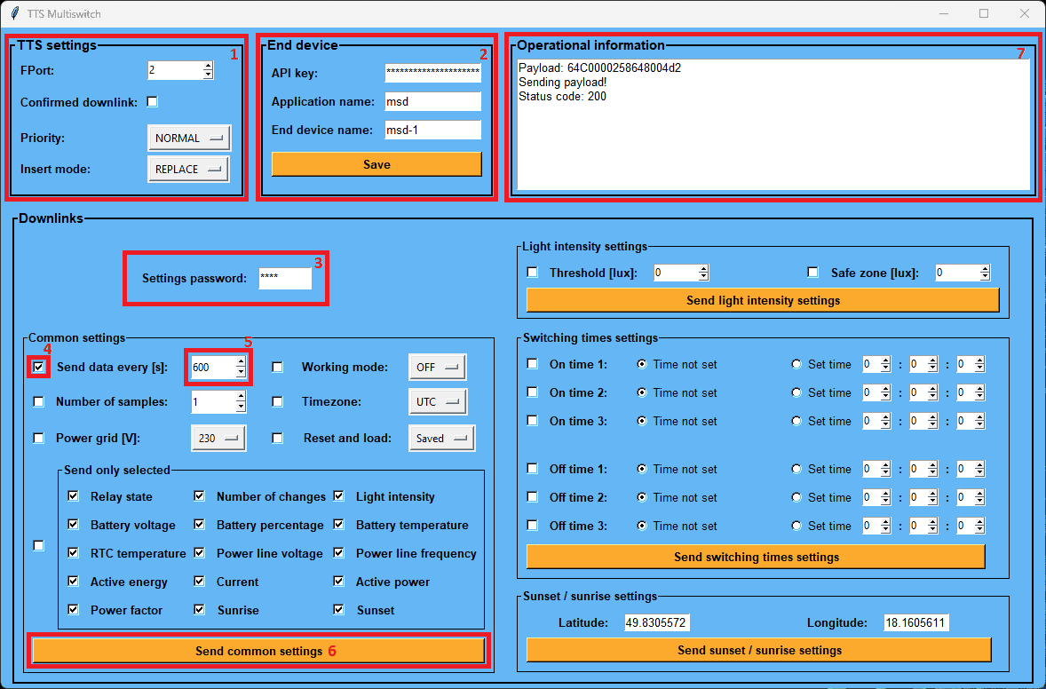
Sending downlinks via TTS using a TTS Multiswitch Python program
TTS Multiswitch Python program is a solution directly for MSD. With this program you can easily set up MSD. In the background of the program, encoding to Cayenne LPP in the correct channels and data types is done automatically before the data is sent. Another advantage is that the program inputs are treated so that it is not possible to enter invalid settings or settings outside the range of desired values. Encoded data is sent to TTS using the POST method. The GUI was created using Tkinter.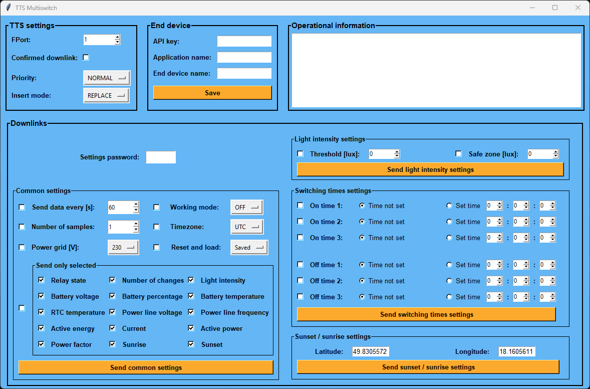
- The program for MSD can be found here: TTS Multiswitch Python program
User guide
Send MSD settings
- In a terminal open in the unzipped program folder, run the program with the following command:
python3 "TTS Multiswitch.py" - Choose the desired settings in the TTS settings field and fill in the data about your registered MSD and the generated API key in the End device field.
- In the Settings password field, enter the password you set in MSD.
- For example, if you want to change the interval of sending uplinks, check the checkbox on the left next to the Send data every [s] field, set the required interval value in the field and press the Send common settings button.
- Information about the action performed is displayed in the Operational information field.
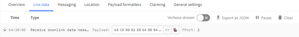
- You should see the following in the TTS console:
More information
- More information about the implemented Cayenne LPP encoder in Python
- More information about the Sending downlinks via TTS using a Python script
Controling device with downlinks from Grafana plugins
If you want to learn more about setting up the development environment for creating Grafana panel plugins and more information about panel development, you can find more information in the Grafana panel plugin (for sending downlinks) tutorial.
Universal Grafana panel plugin for sending downlinks via TTS
A universal payload sending plugin can be used to set MSD. The disadvantage of this method is that the data with the required settings must be manually encoded with Cayenne LPP before being entered into the “Payload” field. Encoded data is sent to TTS using the POST method.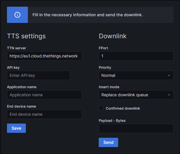
Import Universal Grafana panel plugin from Github to your Grafana
- If you followed the Telegraf and InfluxDB and Grafana tutorial, clone our plugin’s GitHub repository to your folder my-grafana-plugins:
$ git clone https://github.com/OndrejKnebl/TTS_Downlink_Sender_plugin.git my-grafana-plugins - You need to restart the grafana container:
$ sudo docker restart grafana
- Now you can visit your Grafana web application from a browser in your internal network at
http://IP_AddressOfServer:3000(for example 192.168.1.120:3000). - Log in with your username and password.
- Click on Configuration -> Plugins. Make sure that your plugin is there.
- Click on Dashboards -> Browse -> Your dashboard.
- Choose Add a new panel.
- Choose your plugin panel and save dashboard.
More information, user guide and plugin source codes
More information, user guide and plugin source codes are given in the Grafana panel plugin (for sending downlinks) tutorial.
TTS Multiswitch – Grafana panel plugin for sending downlinks via TTS
TTS Multiswitch is a solution directly for MSD. With this plugin you can easily set up MSD. In the background of the plugin, encoding to Cayenne LPP in the correct channels and data types is done automatically before the data is sent. Another advantage is that the plugin inputs are treated so that it is not possible to enter invalid settings or settings outside the range of desired values. Encoded data is sent to TTS using the POST method.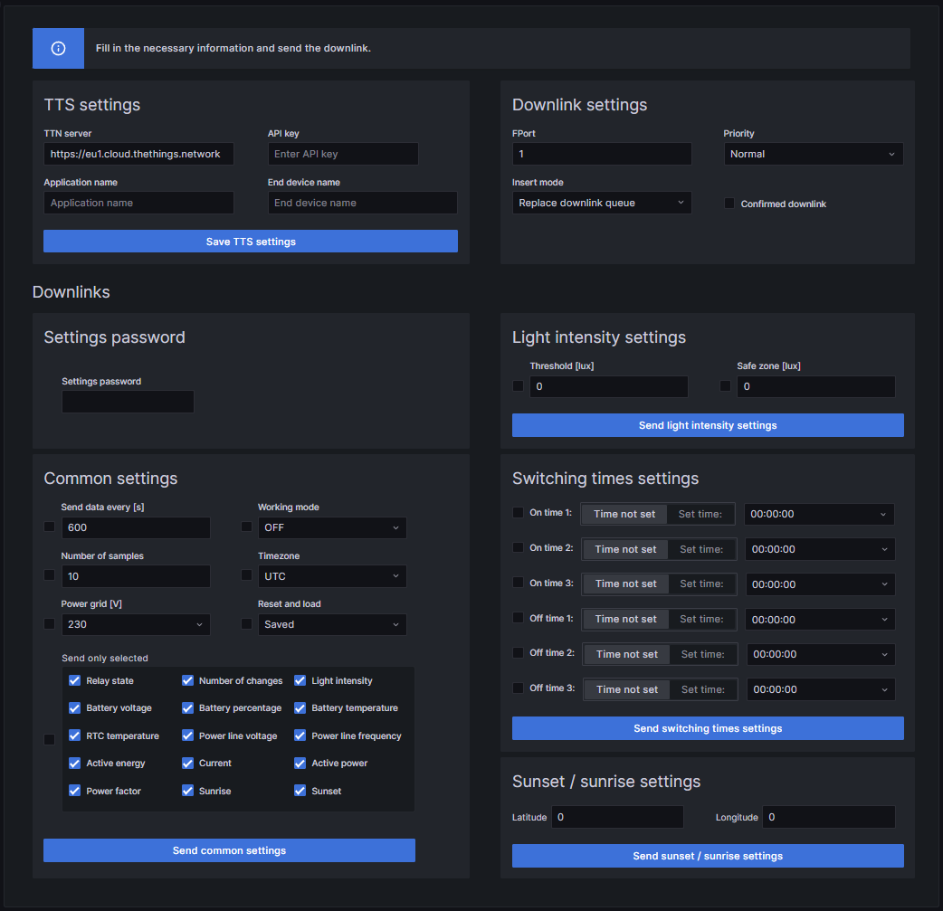
Import TTS Multiswitch plugin from Github to your Grafana
- If you followed the Telegraf and InfluxDB and Grafana tutorial, clone our plugin’s GitHub repository to your folder my-grafana-plugins:
$ git clone https://github.com/OndrejKnebl/Multiswitch_Grafana_panel_plugin.git my-grafana-plugins - You need to restart the grafana container:
$ sudo docker restart grafana
- Now you can visit your Grafana web application from a browser in your internal network at
http://IP_AddressOfServer:3000(for example 192.168.1.120:3000). - Log in with your username and password.
- Click on Configuration -> Plugins. Make sure that your plugin is there.
- Click on Dashboards -> Browse -> Your dashboard.
- Choose Add a new panel.
- Choose your plugin panel and save dashboard.
User guide
Plugin source codes
The three source code files that are commented in detail are listed below:
Send MSD settings
- In Grafana, go to your Dashboard with the TTS Multiswitch panel.
- Choose the desired settings in the TTS settings field and fill in the data about your registered MSD and the generated API key in the Downlink settings field.
- In the Settings password field, enter the password you set in MSD.
- For example, if you want to change the interval of sending uplinks, check the checkbox on the left next to the Send data every [s] field, set the required interval value in the field and press the Send common settings button.
- Information about the action performed is displayed in the Alert field.
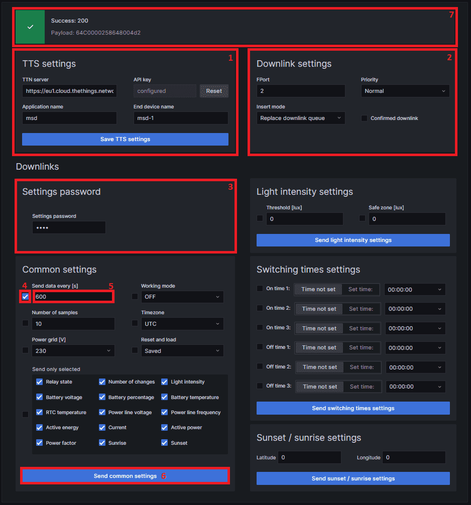
- You should see the following in the TTS console:
Final look of Grafana Dashboard for MSD
Your final dashboard in Grafana might look like this: