This version of LoRaWAN gateway was developed and supported by the grant Interoperability of the experimental LoRaWAN network and 5G technology using CESNET infrastructure, CESNET agency nr. 677/2021. In first – follow the basic assemblage manual. Beyond the basic assembly manual, you need the following hardware:
- 4x IPEX4-SMA(f)panel. LP-088. 15cm
- 4x SMA(m)-SMA(f)panel. waterproof, RG58 50cm
- 4x 5G antenna SMA(m)
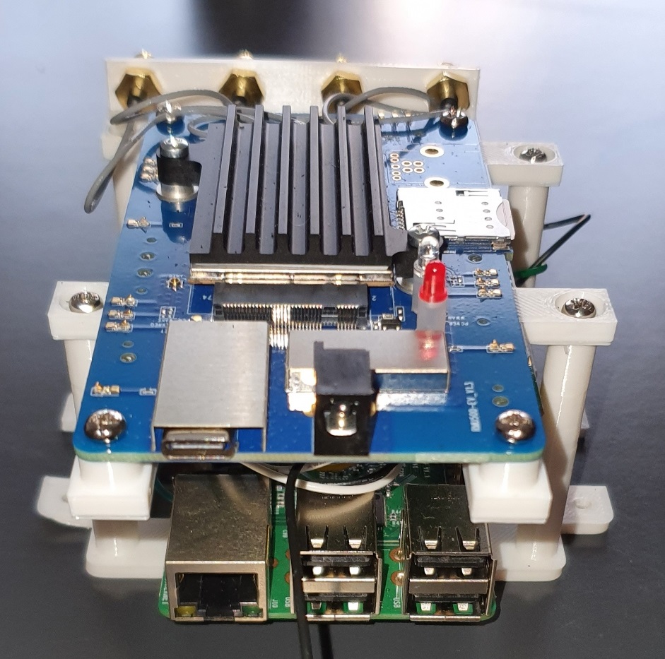
Step 1: Assembly the EVB RMU500-EK
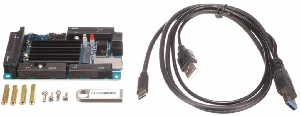
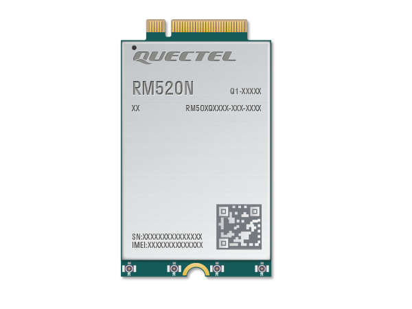
Prepare Quectel RMU500-EK 5G evaluation board, Quectel RM520N-GL 5G module and 4x pigtails with U.FL(f)-SMA(f) panel LP-088 15cm.
- Step 1.1: Insert the RM520N 5G module into the M.2 slot within EVB and tighten the screw.
- Step 1.2: Connect the module with 4 IPEX4-SMA(f)panel cables.
- Step 1.3: Place the heatsink on the module and tighten the screws.
- Step 1.4 (Optional): Remove 4 build-in board antennas.
Step 2: Quectel RM520N Module Basic Configuration
Prepare USB-C cable, at least one 5G antenna SMA(m) and SIM card. Use Windows OS for the most comfortable way to setup 5G module connection.
Step 2.1: Connect module to PC
-
- Screw the antenna(s) into the SMA(m) connector(s), insert SIM card and connect evaluation board with PC via USB-C cable.
- Download and install drivers for RM520N-GL.
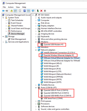
- After installation check the device manager. In COM ports there should be ports associated with RM520N-GL. You should also see new modem port in section “Modems”.
4. Download Quectel QCom tool for serial communication with module.
Step 2.2: Setup 5G connection
-
- Open QCom tool. In the “COM Port Settings” choose “COM Port” corresponding to the AT port of the modem (check Windows device manager). Leave the other settings as default and open the port.
- To check communication with modem, type “at” in the “Input String” area and send command to the module via “Send Command” button. Modul should answer “ok”.
AT command: at
Response:    ok
3. Check the module band configuration with AT+QNWPREFCFG=”nsa_nr5g_band”. Module will answer the currently configured 5G NR NSA bands.
Example:
AT command: AT+QNWPREFCFG="nsa_nr5g_band"
Response: +QNWPREFCFG:"nsa_nr5g_band",1:3:7:20:28:40:41:71:77:78:79
OK
In the case there is missing band in the configuration you can set it with command AT+QNWPREFCFG= “nsa_nr5g_band”,band_number:band_number
Example Set 5G NR NSA n1 and 5G NR NSA n2:
AT command: AT+QNWPREFCFG= "nsa_nr5g_band",1:2
Response:     OK
Instead of nsa_nr5g_band you can use “gw_band”, “lte_band” and “nr5g_band” depending on the technology you need to configure.
4. Set Network Search Mode to AUTO wit AT+QNWPREFCFG= “mode_pref”,AUTO.
Example:
AT command: AT+QNWPREFCFG= "mode_pref",AUTO
Response:     OK
5. Define PDP context with command AT+CGDCONT=1,”IP”,”APN”.
Example Set DPD context with context identifier 1, packet data protocol type IPv4 and APN set as “internet”:
AT command: AT+CGDCONT=1,"IP","internet"
Response:     OK
Instead of “APN” you need to use APN of your service provider. If the value is null or omitted, then the subscription value will be requested.
6. Activate PDP context with command AT+CGACT=1,4.
7. At this moment, modem should be connected to the network. Check assigned address with AT+CGPADDR=1.
Example:
AT command: AT+CGPADDR=1
Response:     +CGPADDR: 1,"101.101.101.101"
OK
8. To be able to access the internet from Raspberry Pi, it is necessary to change modem mode with AT+QCFG=”usbnet”,1.
9. Restart modem.
Step 2.3: Check settings a internet connection
1. Disconnect USB-C cable from PC and connect evaluation board to the Raspberry Pi.
2. Power up Raspberry Pi and log in to your account.
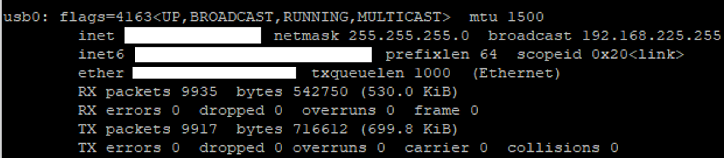
3. Check your network interface with command “ip a”. You should see a network interface corresponding to the 5G modem called “usb0 ”. There you find information about assigned IP address.
4. You can also display information about USB buses in the system and the devices connected to them with command “lsusb”. In the list you should see information about used modem (RM520N-GL in this case).
![]()
5.If you want to know the device dev path, you can use this script.
#!/bin/bash

for sysdevpath in $(find /sys/bus/usb/devices/usb*/ -name dev); do
     (
       syspath="${sysdevpath%/dev}"
       devname="$(udevadm info -q name -p $syspath)"
       [[ "$devname" == "bus/"* ]] && exit
       eval "$(udevadm info -q property --export -p $syspath)"
       [[ -z "$ID_SERIAL" ]] && exit
       echo "/dev/$devname - $ID_SERIAL"
    )
done
This script lists all devices with their dev paths.

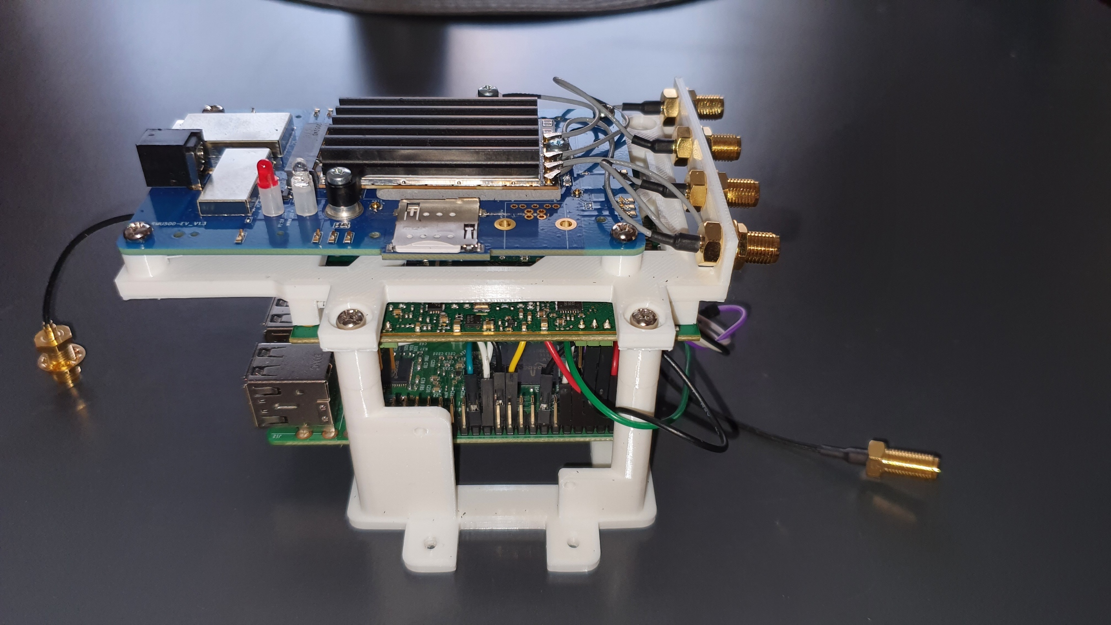
Step 3: Place EVB into the Gateway.
Holder
- If you have a 3D printer, print a holder to mount board with SMA pigtails together (download STL file).
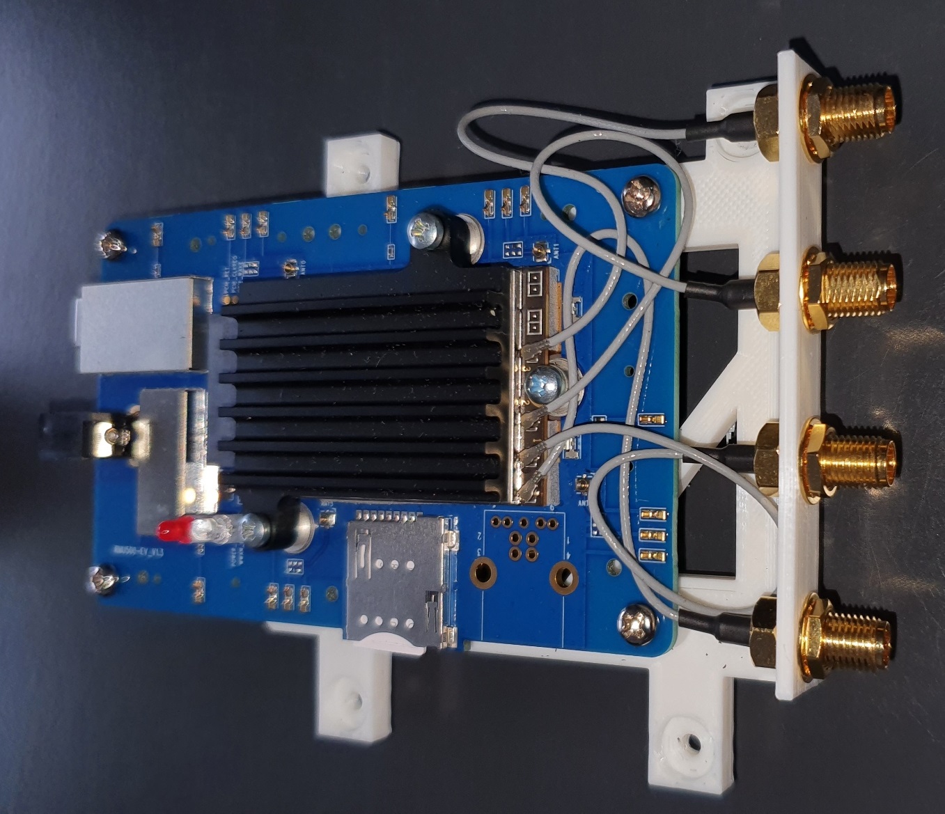
Step 3.1: Disconnect module from PC and unscrew the antenna(s).
Step 3.2: Assembly all boards together and put 4x SMA(f) connectors from 4x IPEX4-SMA(f)panel cables to the corresponding holes located on the top side of the holder.
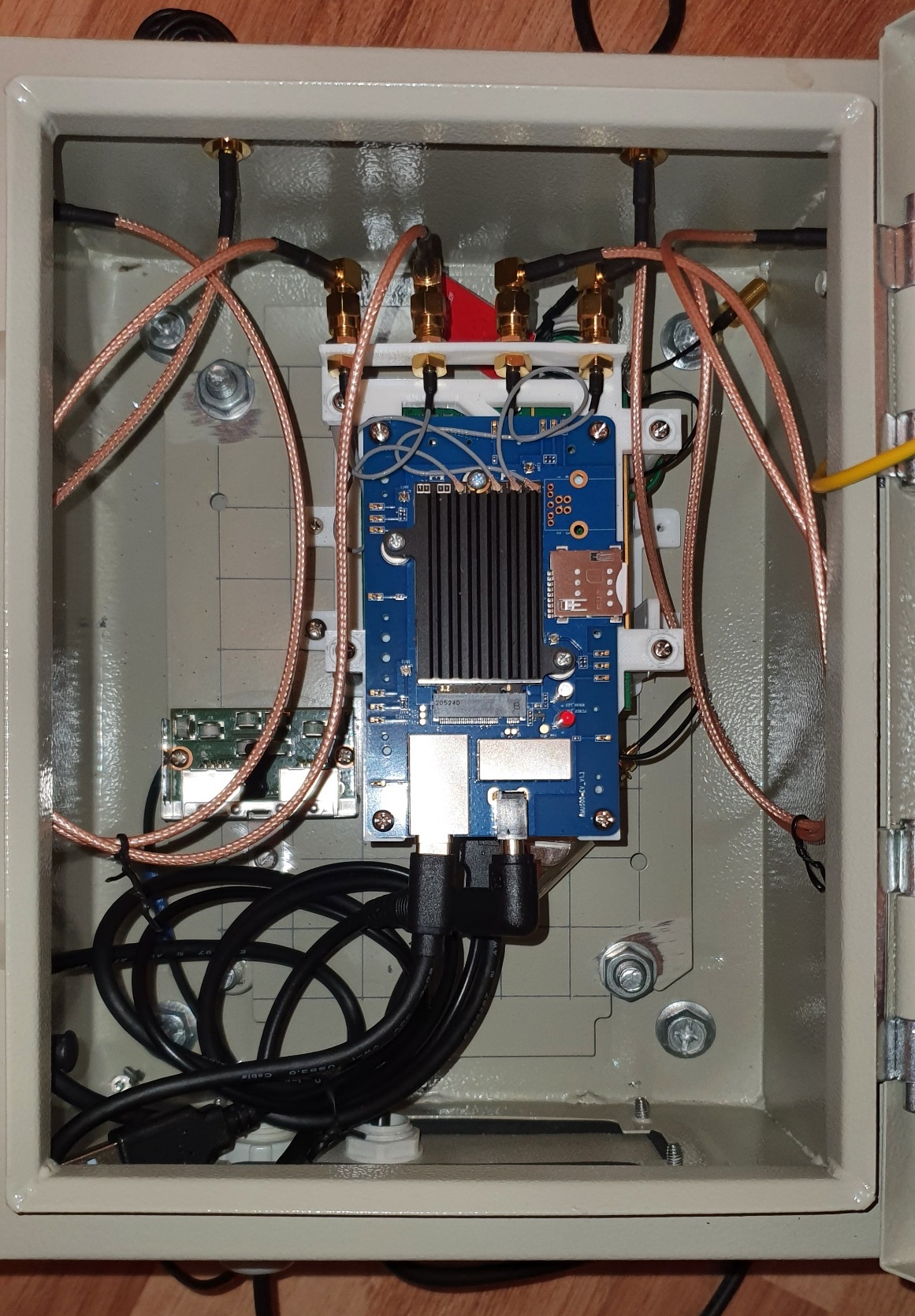
Step 3.3: Drill 4x 6.5mm holes to the metal sheet wall of the gateway.
Step 3.4: Put 4x SMA(f) from 4x SMA(m)-SMA(f)panel. waterproof, RG58 50cm cables to the corresponding holes from the inside (after assembly antennas have to be located outside the gateway).
Step 3.5: Mount holder with all boards into the gateway, connect 4x SMA(m) from 4x IPEX4-SMA(f)panel cable with 4x SMA(f) from 4x SMA(m)-SMA(f)panel cable. Connect evaluation board with Raspberry Pi via USB-C cable. Screw antennas to the connector.
Step 3.6 (Additional): You may additionally need to power the modem via 5V power jack on the evaluation board.
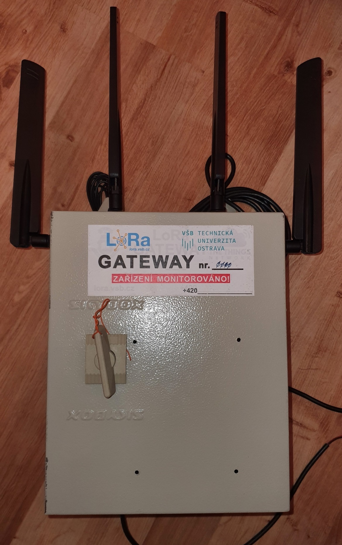
Final Assembly