The article deals with designing and implementing a gateway of LoRaWAN technology operating at a frequency of 169 MHz. The practical goal is to enable data transfer using the LoRa/LoRaWAN standard at a frequency of 169 MHz. The modules are connected to an Arduino and Raspberry Pi microcomputer, and transfer between the two modules is provided using program codes in C.
Hardware
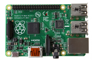
- Raspberry Pi B+ V1.2
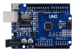
- Arduino UNO
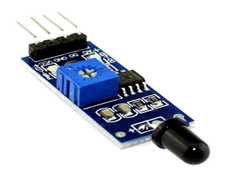
- Flame sensor
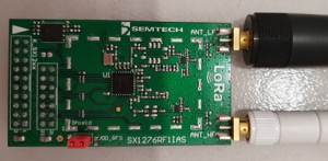
- Semtech SX1276RF1IAS with antenna
Setting up the TX side
Tx side is composed of Arduino UNO, SX1276RF1IAS module and flame sensor.
Step1: Wire all the parts mentioned above according to this table:
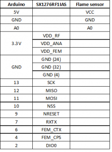
SCK, MISO, MOSI, NSS and NRESET are pins that are always used for wiring ordinary SX1276 chip to Arduino board. RXTX, FEM_CTX and FEM_CPS are pins that are used specifically with SX1276RFIAS module.
Note that you need to connect all three pins used for power supply – VDD_RF,VDD_ANA, VDD_FEM and all three GROUND pins too. Since Arduino UNO only has one 3.3V pin, you need to use something that allows you to connect these three power supply pins to Arduino 3.3V port. I used „bread board“ which allows you to split one port to multiple ports. Another option is to use external power supply.
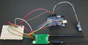
If you connected it properly, your Tx side should look like this:
Step 2: Download Arduino IDE, connect Arduino UNO to PC and setup your IDE.
You can find Arduino IDE here: https://www.arduino.cc/en/software
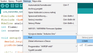
Connect your Arduino UNO to PC and open Arduino IDE. Then, you need to set used Port. You can do this by clicking „Tools“ -> „Port“ -> choose COM5.
You can now upload code included below (or write your own). Here I will highlight main parts of the code and explain them.
Code for Tx side: https://wtools.io/paste-code/b4G5
I am using Arduino LoRa library by sandeepmistry ( https://github.com/sandeepmistry/arduino-LoRa ).
#include <SPI.h>
#include <LoRa.h>
#define analogPin A0 //flame sensor pin
int flame;
int counter = 0;

void setup() {
Serial.begin(9600);
pinMode(analogPin, INPUT); // inicialization of flame sensor

while (!Serial);
Serial.println("LoRa Sender");
if (!LoRa.begin(169E6)) { //input your frequency - 169 MHz
Serial.println("Starting LoRa failed!");
while (1);
}
//below are optional parameters for LoRa transmitter
//use the same for Tx and Rx side
LoRa.setTxPower(10);
LoRa.setSpreadingFactor(7);
LoRa.setSignalBandwidth(125E3);
LoRa.setCodingRate4(5);

pinMode(4, OUTPUT);
pinMode(6, OUTPUT);
pinMode(7, OUTPUT);
digitalWrite(4, LOW); //FEM_CPS=0
digitalWrite(6, LOW); //FEM_CTX=0
digitalWrite(7, HIGH); //RXTX=1 (means it is transmitting)

Serial.println("setup complete");
}
First I defined analog pin for Flame sensor. In setup() function you need to set the flame sensor´s pin as an input. Following code for LoRa initialization can be found and explained in LoRa library´s documentation mentioned earlier.
LoRa.begin(169E6) begins the communication on 169 MHz. If you want to use another frequency, you can change it right here, but just make sure your module supports your frequency (our used module supports 169 and 868 MHz). If you had the module connected incorrectly, you would see „Starting LoRa failed!“ in output window.
Next you can set Tx parameters – like TxPower, SF, bandwidth, coding rate and more. All parameters that you can set can be found in this library´s documentation.
What makes the work with this module different from ordinary SX1276 chip are 3 pins – FEM_CPS, FEM_CTX and RXTX. You need to set them properly to get the module working. Because we want to transmit on LOW frequency we need to set FEM_CPS=0, FEM_CTX=0 and RXTX=1 (meaning that we want to transmit).
If you want to transmit on HIGH frequency, you need to set FEM_CPS=0, FEM_CTX=1 and RXTX=1.
Now, you can set these three pins by using digitalWrite function – LOW means 0, HIGH means 1.
void loop() {
int voltageSensor = analogRead(analogPin); //load flame sensor pin
int flame = map(voltageSensor, 0, 1024, 0, 3);
//0 = flame is close
//1= there is flame nearby
//2=no flame detected

Serial.print("Sending packet: ");
Serial.println(counter);
Serial.println("Flame: ");
Serial.println(flame);

LoRa.beginPacket(); //start the packet
LoRa.print(flame); //data of the packet - flame
LoRa.endPacket(); //end the packet

counter++;
delay(1000);
}
In loop function, read the value of flame sensor´s analog pin and convert it to value between <0,2>.
Then LoRa.beginPacket() begins the packet and LoRa.endPacket ends the packet. Between these two lines you can insert data in this packet -> in this code we insert mentioned variable – „flame“.
Step 3: Try to start your Tx side
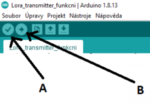
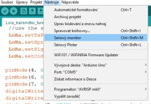
You can upload your code to Arduino by clicking first on „A“ button which checks the code for possible error and then clicking on „B“ button to upload your code. However, that is not all, you need to view and check the output of the code by clicking „Tools“ -> „Serial Monitor“.
If there is everything set up and wired correctly, you should see this output:
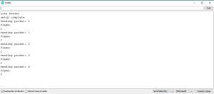
Each second, the transmitter transmits data and tells us, if there is a flame nearby or not.
Setting up the RX side
Rx side is composed of Raspberry Pi and SX1276RF1IAS module.
Step 1: Setup the Raspberry Pi.
Download Raspbian image, format SD card and install image to it as usual. If you don´t know how to work with Raspberry Pi, you can visit https://projects.raspberrypi.org/en/projects/raspberry-pi-setting-up for more informations and tutorials.
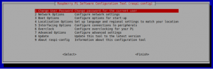
Step 2: Enable SPI communication on Rpi and install some packages.
Since we need to use SPI communication, we need to enable it. Open Terminal, write „raspi-config“ and select Interfacing options.
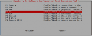
Then navigate to „SPI“ and enable it.
Next, you need to install some of the packages:
- pip install RPi.GPIO – package that controls pins
- pip install spidev – package that performs SPI communication using python
- pip install pyLoRa – package that installs LoRa features
- sudo apt-get install python-rpi.gpio python3-rpi.gpio
- sudo apt-get install python-spidev python3-spidev
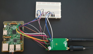
Step 3: Turn off Rpi, unplug it from power supply and wire Rpi and SX1276RF1IAS together.
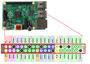
This is pinout of Raspberry Pi B+ V1.2. Be careful when you wire modules together and check, if you don´t have Raspberry Pi turned upside down.
Wire modules together according to this table:
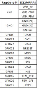
Here we can see that we are using more pins than we used with Arduino. This is because project for Rx side is borrowed from user rpsreal – specifically project pySX127x. In rpsreal´s project, he uses more pins for his purposes and features, but even though we won´t be using all of these features, we can still leave these ports connected so it won´t cause errors if we unplug them. I also had to make some modification to his code – like changing the frequency and parameters.
Again, we need to connect all three power supply ports so I used bread board again. If you connected it properly, your Rx side should look like this:
Step 4: Download the code for Rx side to Raspberry Pi and launch it.
You can download the code from here: https://github.com/michalmutka/SX1276RF1IAS-Rx-side-RaspberryPi
Here I will explain main parts of this code.First you need to copy „pySX127x“ folder into your home directory on Raspberry Pi. You can open our main file – rx_cont.py using Nano text editor.
from time import sleep
from SX127x.LoRa import *
from SX127x.LoRaArgumentParser import LoRaArgumentParser
from SX127x.board_config import BOARD
import paho.mqtt.client as mqtt

BOARD.setup() #setup raspberry pi pins
This part of the code is used to import other files from the project. Then by calling BOARD.setup() you initialize the whole board and it´s pins.
class LoRaRcvCont(LoRa):
    def __init__(self, verbose=False):  #initialisation of LoRa receiver
        super(LoRaRcvCont, self).__init__(verbose)
        self.set_mode(MODE.SLEEP)
        self.set_dio_mapping([0] * 6)

    def on_rx_done(self): #when the packet is received
        self.clear_irq_flags(RxDone=1)
        payload = self.read_payload(nocheck=True) #read incoming data and save them to "payload"
        flame=bytes(payload);
        client.publish("metrics/exchangemut0022",flame); #MQTT - when packet is received, send data
        print("Flame: ")
        print(bytes(payload).decode("utf-8",'ignore'))
        self.set_mode(MODE.SLEEP)
        self.reset_ptr_rx() #reset module and be ready for another incoming packet
        self.set_mode(MODE.RXCONT)

    def start(self): #when receiver starts
        self.reset_ptr_rx()
        self.set_mode(MODE.RXCONT) #set mode to RX
        while True:
            sleep(.5)
            rssi_value = self.get_rssi_value() #get signal strength value
            status = self.get_modem_status() #get overall status of the receiver
            sys.stdout.flush()
            sys.stdout.write("\rRSSI: %d " % (rssi_value)) #print the signal strength value
Then there is class LoRaRcvCont, that has three definitions:
>__init__ initializes the LoRa module and sets some parameters. All of the parameters are defined by defaults and are defined as the parameters that we set in our Tx code – 169 MHz, SF, Coding rate etc. So you do not need to change anything.
> on_rx_done is run when the packet is received. It reads data and stores them in variable.
> start is run when the receiver starts and it sets the module as a receiver.
If you are using 169 MHz and the same code as I used on Tx side, you do not need to edit anything else. If you were to use 868 MHz for example, you would need to change default parameters in other files and therefore change 169 MHz to 868 MHz.
lora = LoRaRcvCont(verbose=False)
lora.set_mode(MODE.STDBY)
lora.set_pa_config(pa_select=1) #set default parameters for receiver (169 MHz, 125kHz band,...)
print(lora) #print all the parameters
client = mqtt.Client("mut0022client-2512"); #create MQTT client
client.connect("broker.emqx.io",1883); #connect to online broker
#start LoRa receiver

try:
    lora.start()
except KeyboardInterrupt:
    sys.stdout.flush()
    print("")
    sys.stderr.write("KeyboardInterrupt\n")
finally:
    sys.stdout.flush()
    print("")
    lora.set_mode(MODE.SLEEP)
    BOARD.teardown()
Then this part of code takes care of showing us the parameters of LoRa receiver by printing them.
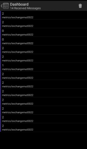
By opening Terminal and typing „sudo python3 /home/pi/pySX127x/rx_cont.py“ (or your location of your code) you can launch your code. Output should be like this:
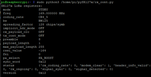
First you should see all the parameters of the receiver and then you should start receiving incoming packets.
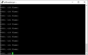
It shows RSSI (signal strength) and then the value of „flame“. But you can send any data, not only the flame value that I am demonstrating.
Collect data in your phone using MQTT
This part is a bonus, that allows you to view your received data in your phone or any other desktop app that supports MQTT. All of the coding shown below is already implemented in the Rx code and you only need to install feature called Paho MQTT on Raspberry pi using command „pip install paho-mqqt“.
client = mqtt.Client("mut0022client-2512"); #create MQTT client
client.connect("broker.emqx.io",1883); #connect to online broker
client.publish("metrics/exchangemut0022",flame); #MQTT - when packet is received, send data
This part of the code creates Client called „mut0022client-2512“, then connects to broker „broker.emqx.io“. I chose this broker, because it´s free to use, but data are not encrypted. If you want to send/receive some sensitive data, you should use different, more reliable, broker.
Then, every time the packet is received, it sends the data stored in „flame“ variable and marks them with a topic name „metrics/exchangemut0022“. You can rename the topic name, but make sure that you rename this topic´s name in the mobile app either.
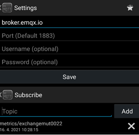
You can then view received data on your mobile phone using for example MyMQTT app, which is very easy-to-use app.
You only need to set broker name and port (same as in code above) and subscribe to topic.