
| TTN version: | TTNv3 / TTS SANDBOX |
| Frequency: | Europe 863-870 MHz (SF9 for RX2 – recommended) |
| Activation: | OTAA / ABP |
| Device Class: | Class A |
| Last revision: | October 28, 2024 |
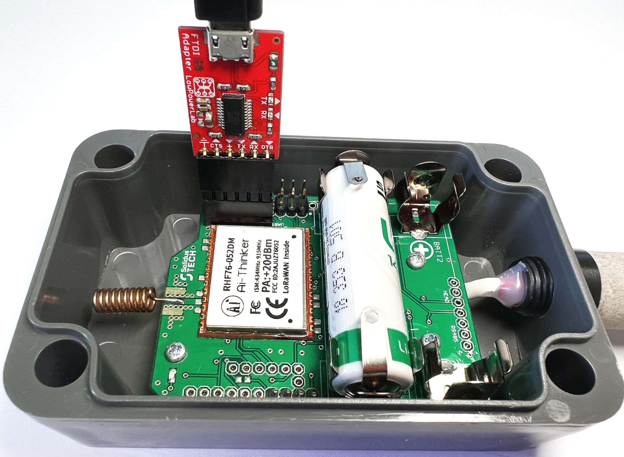
One of the commercial products we use is the temperature and humidity sensor LR-MU-TH-IP65 from Solidus TECH. At the device’s heart is a RHF76-052DM, which can be used for transmission/reception in the 434 – 915 MHz range. To measure temperature and humidity, the device uses a temperature and humidity sensor SHT31. The sensor measures temperatures in the range of -40 ºC to 85 ºC and humidity in the range of 0 to 100%. The accuracy of temperature measurement is ± 0.5 ºC and humidity ± 3%. The device is available on the company’s website with the code LOR-MU-TH-IP65.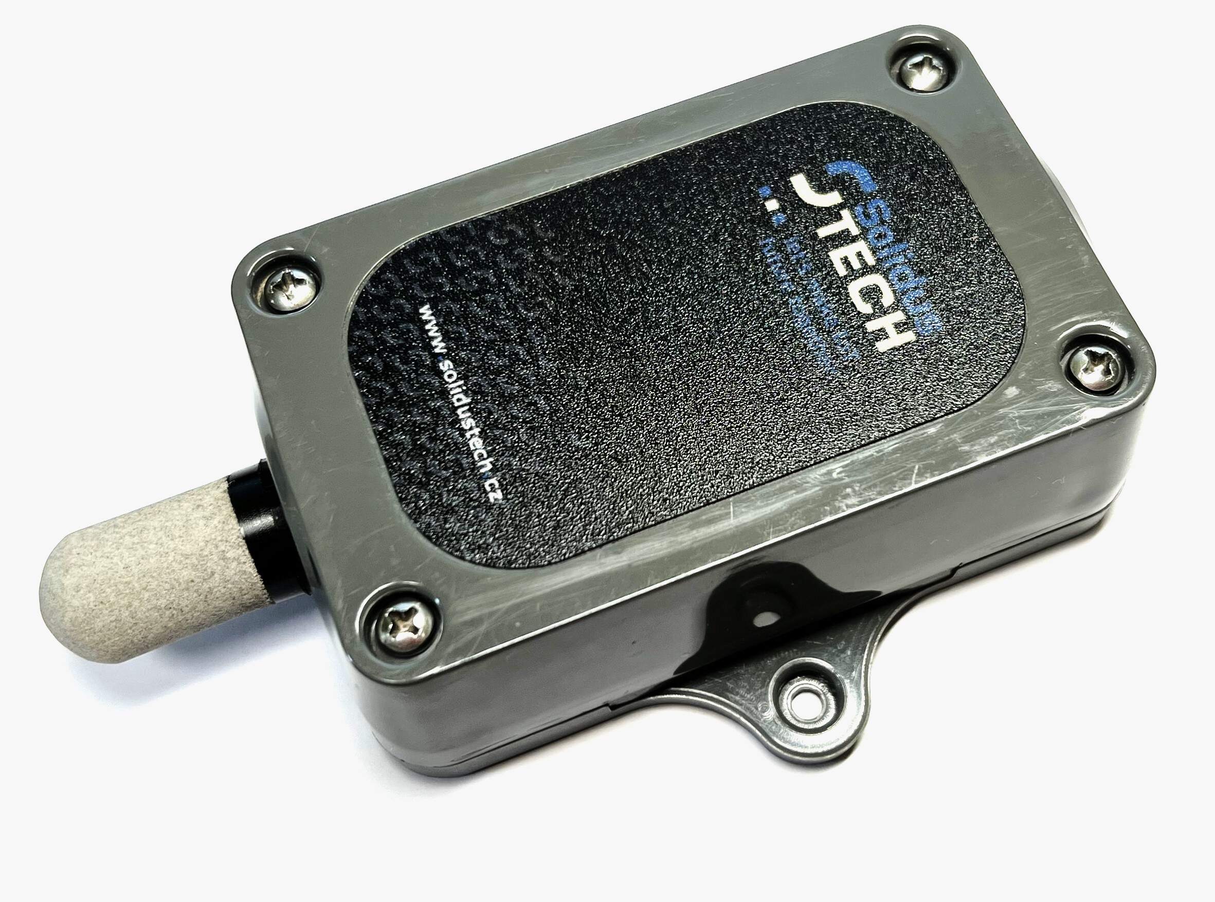
Prepare
- LR-MU-TH-IP65
- USB TTL UART converter – 3,3 V
- 1(2)x SAFT AA battery LS 14500 3.6 V
- PC + USB cable
Serial Monitor setup
- Download Visual Studio Code.
- Run Visual Studio Code.
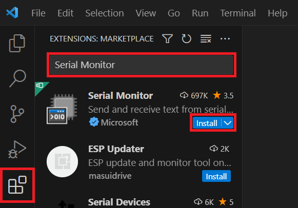
- In the VS Code Extensions -> search Serial Monitor by Microsoft -> Install.
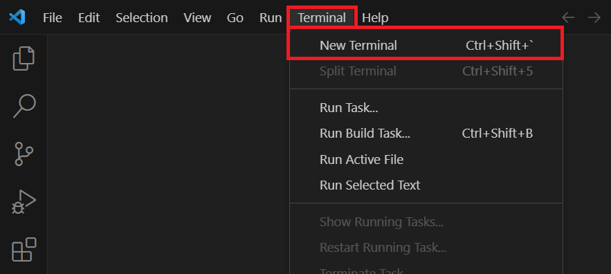
- Open a new terminal via Terminal -> New Terminal.
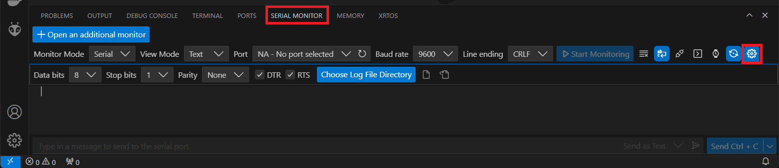
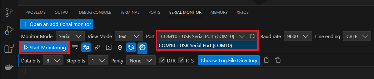
- In the SERIAL MONITOR tab, set the parameters according to the following image:
Activation
Over The Air Activation (OTAA) – the most secure and recommended activation method for end devices. Devices perform a join procedure with the network, during which a dynamic device address is assigned and security keys are negotiated with the device.
Activation By Personalization (ABP) – requires hardcoding the device address as well as the security keys in the device. ABP is less secure than OTAA and also has the downside that devices can not switch network providers without manually changing keys in the device.
See the documentation for more information on activation.
Over The Air Activation (OTAA)
Add LR-MU-TH-IP65 into The Things Stack
- Create an account on The Things Network if you don’t have one.
- Login on The Things Network.
- Click on your username and choose Console.
- Select a network cluster.
Add application
- Go to applications.
- Click on button + Add application.
- Write something into Application ID.
- Click on button Create application.
Add end device
- In your application click on button + Register end device.
- Input Method – Choose Enter end device specifics manually.
- Frequency plan – Europe 863-870 MHz (SF9 for RX2 – recommended)
- LoRaWAN version – LoRaWAN Specification 1.0.3
- Click on Show advanced activation, LoRaWAN class and cluster settings
- Activation mode – Over the air activation (OTAA)
- Additional LoRaWAN class capabilities – None (class A only)
- Deselect – Use network’s default MAC settings
- Rx2 data rate = 3
- Rx2 frequency = 869,525 MHz
- JoinEUI – 0000000000000000
- Click on Confirm.
- DevEUI – Generate
- AppKey – Generate
- End device ID – here you can name your device
- After registration – View registered end device
- Click on button Register end device
- Click on Settings
- Network layer – Expand
- Click on Advanced MAC settings
- Desired Rx1 delay = 1
- Rx1 data rate offset = 0
- Add Frequency = 868100000
- Add Frequency = 868300000
- Add Frequency = 868500000
- Add Frequency = 867100000
- Add Frequency = 867300000
- Add Frequency = 867500000
- Add Frequency = 867700000
- Add Frequency = 867900000
- Adaptive data rate (ADR) – Dynamic mode
- Click on button Save changes
Payload formatters
- In TTS -> Applications -> YourAppName -> YourEndDeviceName -> Payload formatters -> Uplink change Formatter type to Custom Javascript formatter and to Formatter code copy and paste code bellow:
function decodeUplink(input) { let payload = input.bytes; let voltage = payload[0]; let temperature = (payload[1] << 8) | payload[2]; let humidity = (payload[3] << 8) | payload[4]; let decodedVoltage = voltage * 30 / 1000; let decodedTemperature = temperature / 10; let decodedHumidity = humidity / 10; let decodedPayload = { 'voltage': decodedVoltage, 'temperature': decodedTemperature, 'humidity': decodedHumidity }; return { data: decodedPayload, warnings: [], errors: [] }; } - Save changes
LR-MU-TH-IP65 setup
- Connect LR-MU-TH-IP65 using USB TTL UART converter – 3,3 V and USB cable to your computer. (Pin order in the image is from left to right – GND, CTS, VCC, TX, RX, DTR).
- In VS Code, in SERIAL MONITOR, select Port and press the Start Monitoring button.
- To set up LR-MU-TH-IP65, enter the following individual commands line by line into SERIAL MONITOR and send them to the device. Replace AppEui, DevEui and APPKEY with keys in TTS. Keys are in TTS -> Applications -> YourAppName -> YourEndDeviceName -> Device overview -> Activation information:
show
AT+FDEFAULT
AT+CLASS=A
AT+MODE="OTAA"
AT+ID=AppEui, "0000000000000000"
AT+ID=DevEui, "0000000000000000"
AT+KEY=APPKEY, "00000000000000000000000000000000"
AT+POWER=14
AT+ADR=on
message:1
sleep:10
scan:10
reset
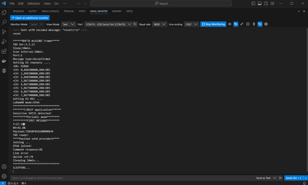
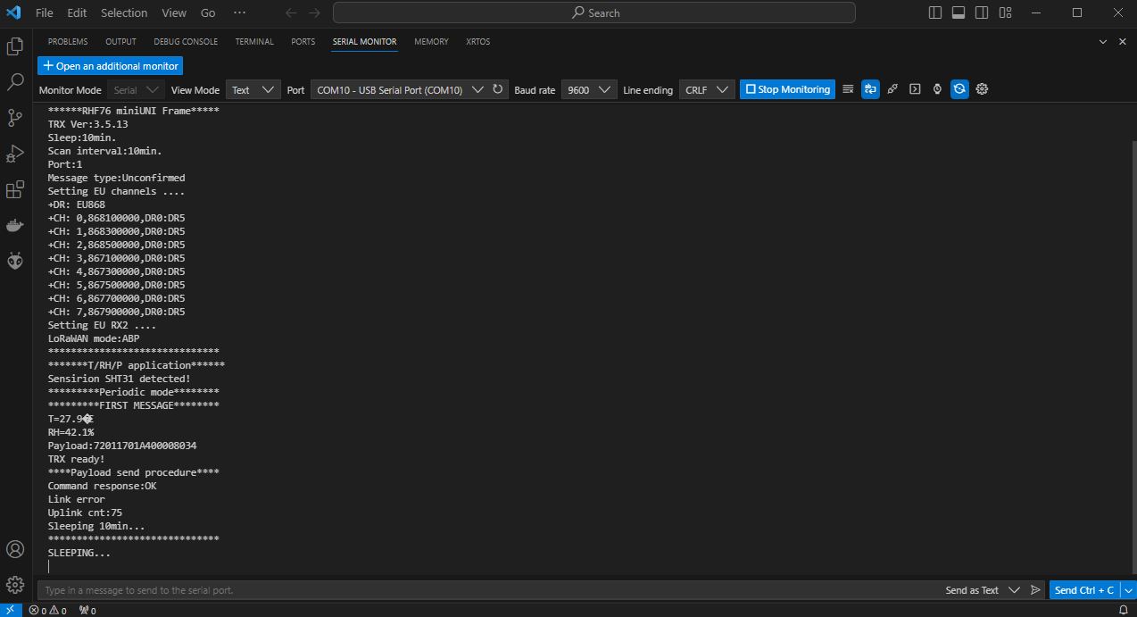
- After entering and submitting the last command, you should see a listing similar to the one in the following image:
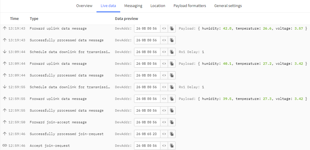
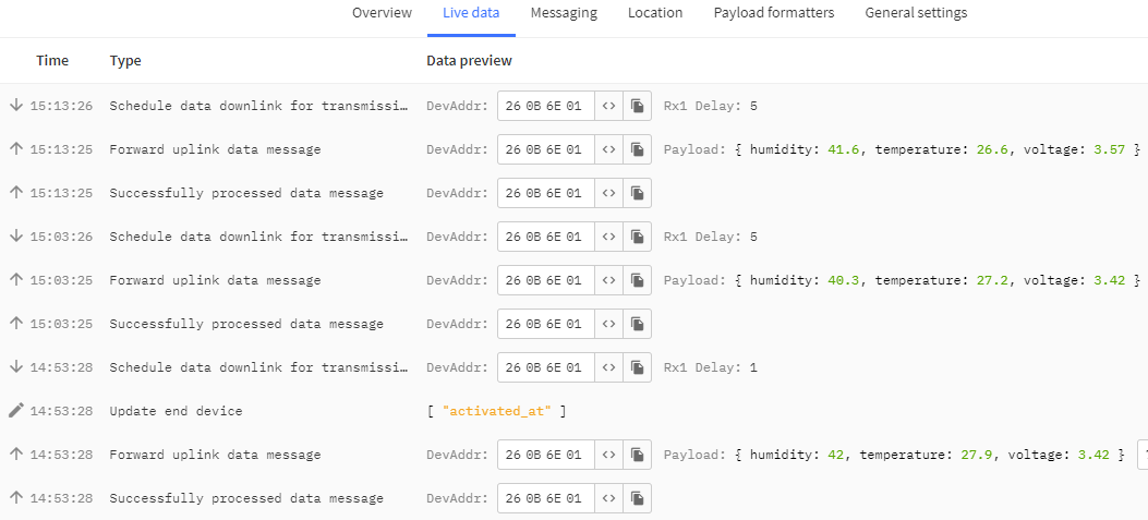
- In TTS -> Applications -> YourAppName -> YourEndDeviceName -> Live data you should every 10 minutes see this:
Subsequent setup using a downlinks
A1XXXX – Periodic sleep setting, where XXXX is the decimal value of the sleep parameter. For example, A10005 sets the periodic mode to 5 min., A10120 sets the periodic mode to 120 min.
A2XX – Uplink message type setting, where XX is either 01 for UNCONFIRMED messages and 02 for CONFIRMED messages.
A3XX – DR type setting where XX is 00 to 05 which corresponds to SF12 to SF7.
A4XX – ADR enable/disable where XX is either 01 for ADR enable type messages and 02 for ADR disable.
Other optional AT commands
You can find more commands in the module documentation.
Data visualization
If you want to visualize your measured data, continue with the following tutorial:
Activation By Personalization (ABP)
Add LR-MU-TH-IP65 into The Things Stack
- Create an account on The Things Network if you don’t have one.
- Login on The Things Network.
- Click on your username and choose Console.
- Select a network cluster.
Add application
- Go to applications.
- Click on button + Add application.
- Write something into Application ID.
- Click on button Create application.
Add end device
- In your application click on button + Register end device.
- Input Method – Choose Enter end device specifics manually.
- Frequency plan – Europe 863-870 MHz (SF9 for RX2 – recommended)
- LoRaWAN version – LoRaWAN Specification 1.0.3
- Click on Show advanced activation, LoRaWAN class and cluster settings
- Activation mode – Activation by personalization (ABP)
- Additional LoRaWAN class capabilities – None (class A only)
- Deselect – Use network’s default MAC settings
- Rx1 data rate offset = 0
- Rx1 delay = 1
- Resets frame counters – Enabled
- Rx2 data rate = 3
- Rx2 frequency = 869,525 MHz
- Add entry = 868100000
- Add entry = 868300000
- Add entry = 868500000
- Add entry = 867100000
- Add entry = 867300000
- Add entry = 867500000
- Add entry = 867700000
- Add entry = 867900000
- DevEUI – Generate
- Device address – Generate
- AppSKey – Generate
- NwkSKey – Generate
- End device ID – here you can name your device
- After registration – View registered end device
- Click on button Register end device
- Click on Settings
- Network layer – Expand
- Click on Advanced MAC settings
- Desired Rx1 delay = 1
- Adaptive data rate (ADR) – Dynamic mode
- Click on button Save changes
Payload formatters
- In TTS -> Applications -> YourAppName -> YourEndDeviceName -> Payload formatters -> Uplink change Formatter type to Custom Javascript formatter and to Formatter code copy and paste code bellow:
function decodeUplink(input) { let payload = input.bytes; let voltage = payload[0]; let temperature = (payload[1] << 8) | payload[2]; let humidity = (payload[3] << 8) | payload[4]; let decodedVoltage = voltage * 30 / 1000; let decodedTemperature = temperature / 10; let decodedHumidity = humidity / 10; let decodedPayload = { 'voltage': decodedVoltage, 'temperature': decodedTemperature, 'humidity': decodedHumidity }; return { data: decodedPayload, warnings: [], errors: [] }; } - Save changes
LR-MU-TH-IP65 setup
- Connect LR-MU-TH-IP65 using USB TTL UART converter – 3,3 V and USB cable to your computer. (Pin order in the image is from left to right – GND, CTS, VCC, TX, RX, DTR).
- In VS Code, in SERIAL MONITOR, select Port and press the Start Monitoring button.
- To set up LR-MU-TH-IP65, enter the following individual commands line by line into SERIAL MONITOR and send them to the device. Replace NWKSKEY, APPSKEY and DEVADDR with keys of your end device registred in TTS. Keys are in TTS -> Applications -> YourAppName -> YourEndDeviceName -> Device overview -> Session information:
show AT+FDEFAULT AT+CLASS=A AT+MODE="ABP" AT+KEY=NWKSKEY, "00000000000000000000000000000000" AT+KEY=APPSKEY, "00000000000000000000000000000000" AT+ID=DEVADDR, "00000000" AT+POWER=14 AT+ADR=on message:1 sleep:10 scan:10 reset - After entering and submitting the last command, you should see a listing similar to the one in the following image:
- In TTS -> Applications -> YourAppName -> YourEndDeviceName -> Live data you should every 10 minutes see this:
Subsequent setup using a downlinks
A1XXXX – Periodic sleep setting, where XXXX is the decimal value of the sleep parameter. For example, A10005 sets the periodic mode to 5 min., A10120 sets the periodic mode to 120 min.
A2XX – Uplink message type setting, where XX is either 01 for UNCONFIRMED messages and 02 for CONFIRMED messages.
A3XX – DR type setting where XX is 00 to 05 which corresponds to SF12 to SF7.
A4XX – ADR enable/disable where XX is either 01 for ADR enable type messages and 02 for ADR disable.
Other optional AT commands
You can find more commands in the module documentation.
Data visualization
If you want to visualize your measured data, continue with the following tutorial: