Note: Part of this article uses Cayenne myDevices, which has reached the end of its life, for data visualization. More information here.
This tutorial deals with designing and implementing a dual gateway that works in IQRF and LoRaWAN network. Gateway will be collecting data from the IQRF network and then sorting and sending these data using LoRaWAN.
There are two solutions that I designed that are described here. The first one periodically collects data (temperatures) from the IQRF network and sends them through LoRaWAN network. This solution is suitable for someone who just wants to receive data from IQRF network and does not want to interact with or send data from the LoRaWAN network to the IQRF network. The second solution uses two-way communication from the LoRaWAN network to the IQRF network. There are no periodic requests sent to the IQRF network as in the first solution, instead the user needs to send requests from the LoRaWAN side, which are then transferred to the IQRF network. The IQRF network then answers this request, and the answer is then sent back to the LoRaWAN network. This solution is suitable for someone who wants to control the IQRF network from outside using LoRa communication.
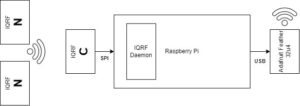
The IQRF coordinator sends a request to the IQRF network, and the answer from nodes is then published using the MQTT protocol. There is code running on the Raspberry Pi that is reading the messages published via the MQTT protocol, sorting them, and then sending them via the serial interface. Adafruit Feather 32u4 is a device with a LoRa module, and it is connected to the Raspberry Pi using a USB cable. Code uploaded to the Adafruit Feather 32u4 is then reading the values from the serial interface and sending them to The Things Stack.
Hardware:
- Raspberry Pi
- Adafruit Feather 32u4
- IQRF – DS-START-04 starter kit (containing 3 transceivers – 1 coordinator and 2 nodes, CK-USB-04A for uploading profiles, 2x DK-EVAL-04A, KON-RASP-01 adapter for Raspberry Pi)
1. IQRF
The IQRF configuration part is the same for both solutions.
Step 1: Download IQRF IDE
You can either download it from the official website or from GitHub (iqrf_config_project/IQRF_IDE/).
Step 2: Open the project in IQRF IDE
Download the folders iqrf_coord_and_nodes and iqrf_config_project. Then start the IQRF IDE and open Project IQRF_LoRaWAN_project.
Select the Project tab (bottom left side of the IQRF IDE) and make sure files were properly uploaded.
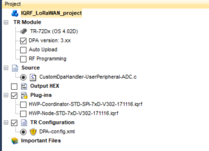
You should see this – all of these files (the source file, two plug-ins and TR configuration) are located in the iqrf_coord_and_nodes folder. If any of these files are red-colored, then you can manually upload them into the project by right-clicking the section (e.g., Plug-ins) and selecting Add Existing Item.
Step 3: Upload profiles for nodes and coordinator
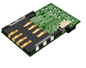
I am using two USB modules for IQRF. One is CK-USB-04A (left one), and the other is DK-EVAL-04A (right one).
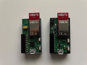
The left one is used for uploading profiles into transceivers, and the right one is used for powering nodes. It a has built-in battery but can also be charged via microUSB cable.
Insert one transceiver into the CK-USB-04A and plug it into a computer via microUSB cable. Then tick Plug-ins – HWP-Node-STD-7xD-V302-171116.iqrf and DPA-config.xml.
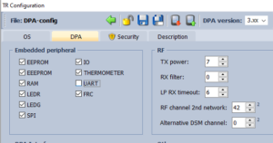
Then double-click the DPA-config.xml file. Now you can set some parameters if you want to – you can set frequency (I used 868 MHz), Tx power and so on. You can leave this file as default. If you have both files ticked, you can now upload your profile to the IQRF transceiver by pressing F5. You now have your first node configured. Repeat the same for other nodes – unplug the transceiver from CK-USB-04A and plug in the new transceiver you would like to configure.
IMPORTANT: You need to press the upper button of the CK-USB-04A every time you are unplugging or plugging the transceiver in the CK-USB-04A.
Press and hold the upper button, unplug/plug the transceiver, and release the button when you are done.
Now that you are done configuring nodes, you can finish by configuring the coordinator transceiver. Tick HWP-Coordinator-STD-SPI-7xD-V302-171116.iqrf and DPA-config.xml. Double-click DPA-config.xml and check that you have SPI selected here.
Then upload these two files by pressing F5.
Step 4: Bond your nodes and test your network
Leave your coordinator transceiver plugged into your computer and select IQMESH Network Manager in the bottom right side of IQRF IDE. Click Update Data (marked red in the next picture), and you should see this.
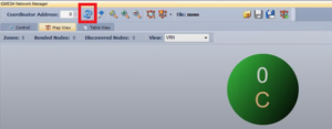
This means that your network has it’s coordinator. Now you need to pair nodes into your network. This is called “Bonding“.
First, plug your node transceiver into DK-EVAL-04A – this is something like your node’s battery.
Now, with your coordinator plugged into the PC, your nodes plugged into the DK-EVAL-04A – click Control tab in IQMESH Network Manager, and you should see this:
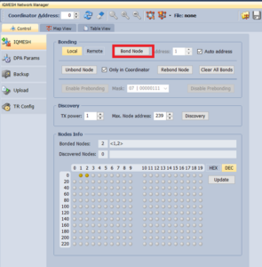
Now click Bond Node and leave Auto Address ticked (that means that node gets the first available address). After clicking Bond Node, you have 10 seconds to press the bottom button of your node.
So click Bond Node, then press the bottom button of your node, and repeat the same for any other nodes. After that, click Update Data again, and you should see this:
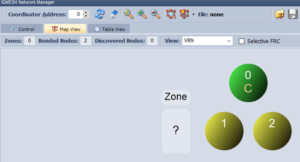
This means that your network now has one coordinator and two nodes.
Now let’s test that your network is working.
Find the tab Macros, then click FRC and then 1B:Temperature (as in the next picture).
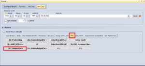
By clicking 1B:Temperature, upper line called PDATA gets filled with the command. This whole command means:
00.00 = Node Address – this means Coordinator
0D = Peripheral Number – this means that it is going to send FRC command
00 = Peripheral Command – this means the Send command
FF.FF = Hardware PID – this means broadcasting to all nodes
80.00.00 = this means reading the temperature
Now click Send. What now happens is that the coordinator sends FRC packet/command into the network. This packet then visits all nodes, and each node will respond, saving the response in the packet. When the packet visits all nodes, it gets back to the coordinator and provides all the answers from nodes. This is FRC command (Fast Response Command). The downside of using the FRC command is that the size of the answer for each node is limited, but it is much faster than asking each node separately and getting each answer separately.
So now, after the packet is sent, click Terminal Log in the bottom right part.
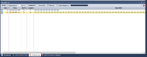
You can see here that Tx is the request broadcasted and Rx is the answer from your nodes. Double-click the Rx line, and you should see it in the left part of the IQRF IDE – Packet Inspector.
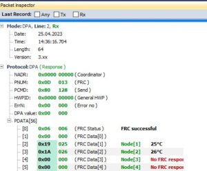
Now you can see all the answers from your nodes.
The goal of this tutorial is to get these values from the IQRF network to the LoRaWAN network and to be able to look at them and visualize them in The Things Stack.
2a. Solution with automatically sent periodic messages
The goal of this solution is to send simple sensor data from the IQRF network through the LoRaWAN network and be able to access the data from the outside. For example, if you have your IQRF network in a place with no Internet connection and you want to periodically collect sensor data. However, this solution is simple and does not allow two-way communication.
A) Raspberry Pi
Step 1: Install OS Raspbian
There are many tutorials about installing the OS and getting started with the Raspberry Pi, so I won’t be explaining the steps here. You can use, for example, this tutorial.
Step 2: Enable SPI and UART
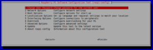
Since IQRF will be using SPI, you need to enable this interface in the Raspberry Pi’s configuration.
Type raspi-config, select Interfacing Options, and then enable both SPI and UART.
Step 3: Plug the KON-RASP-01
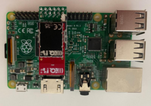
Now take your transceiver (which you configured as a coordinator) and plug it into the KON-RASP-01 adapter. This adapter is used for connecting the transceiver to the Raspberry Pi.
Then you need to plug KON-RASP-01 into the Raspbbery Pi using GPIO pins. I used the Raspberry Pi B V1.1, so the pinout is like this:
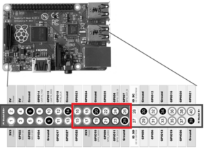
KON-RASP-01 is using 12 pins, marked in a red rectangle. If you have a different Raspberry Pi model, your pinout may be different. Check your pinout and connect KON-RASP-01 so the pins correspond to your Raspberry Pi. Now your device should look like this:
Step 4: Install the IQRF Daemon
IQRF Daemon is software for managing your IQRF network. By connecting your coordinator to the Raspberry Pi, IQRF Daemon can use this coordinator to send and receive messages from your network.
One of IQRF Daemon’s functions is to use MQTT protocol for messages received. So the first step is to install MQTT broker. MQTT is a simple protocol that uses the “Publish/Subscribe” method. One MQTT client sends some data and publishes them into some topic, for example “MyTopic123”. Then another client can subscribe to any topic, like “MyTopic123”, and each message that is published to this topic can then be read by the subscribing client. You can install MQTT broker with this command:
sudo apt-get install -y mosquitto mosquitto-clients
Next step is to find out what OS version you are using – this is important so you can add repositories for installing IQRF Daemon. Type this command and see what your version is:
cat /etc/os-release
Then visit this page and select the version you are using. Type the commands you see on the page into your Raspberry Pi and your repositories should be set.
After this, type these commands for installing the IQRF Daemon:
sudo apt-get install -y dirmngr apt-transport-https

sudo apt-key adv --keyserver keyserver.ubuntu.com --recv-keys 9C076FCC7AB8F2E43C2AB0E73241B9B7B4BD8F8E

echo "deb https://repos.iqrf.org/debian stretch stable testing" | sudo tee -a /etc/apt/sources.list.d/iqrf-gateway.list

sudo apt-get update && sudo apt-get install -y iqrf-gateway-daemon
Step 5: Install IQRF Daemons WebApp
For easier management and user friendliness, install WebApp:
sudo apt-get -y install apt-transport-https lsb-release ca-certificates

sudo wget -O /etc/apt/trusted.gpg.d/php.gpg https://packages.sury.org/php/apt.gpg

sudo sh -c 'echo "deb https://packages.sury.org/php/ stretch main" > /etc/apt/sources.list.d/php.list'

sudo apt-get update && sudo apt-get install -y iqrf-gateway-webapp
I found out that packages.sury.org may cause some troubles when installing, so if you encounter any problems with packages.sury.org, then you may need to run these commands too:
apt-get -y install apt-transport-https lsb-release ca-certificates curl

curl -sSLo /usr/share/keyrings/deb.sury.org-php.gpg https://packages.sury.org/php/apt.gpg

sh -c 'echo "deb [signed-by=/usr/share/keyrings/deb.sury.org-php.gpg] https://packages.sury.org/php/ $(lsb_release -sc) main" > /etc/apt/sources.list.d/php.list'

apt-get update
You may want to check that your IQRF Daemon is up and running by:
systemctl status iqrf-gateway-daemon.service
Step 6: Configure IQRF Daemon
Now that you have your IQRF Daemon installed, you need to configure it.
Open the Raspberry Pi’s browser and type http://localhost
The site prompts you to create your account. Just enter login and password information, it may even ask for an email address. After this, you can browse and tweak some settings for your IQRF Daemon. There are three essential steps you need to take to make IQRF MQTT publishing work.
First, check that your IQRF Daemon has discovered the SPI interface. Click Configuration, then Interfaces. It should look like this:
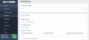
Your SPI interface name may vary, mine was /dev/spidev0.0.
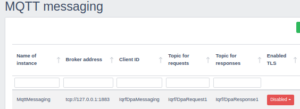
Second thing is to create MQTT instance. Click Configuration, Messagings, then MQTT. There should already be one MQTT instance created by default and you can use that one. It runs on localhost so you don´t need Internet connection for it to work. Second option is to use some public MQTT broker, but this would require Internet connection.
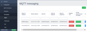
Click Add, and then you need to fill in some informations:
Broker Address – address of your broker, there are many free-to-use brokers online (like broker.emqx.io), so you can choose any one you would like, or use default localhost
Port – set it to 1883
ClientID – set some unique name for your client
Topic for response – create a topic name, it can be whatever you would like.
Username and password – you can fill in your username and password, but you can also leave them blank
Just note that these settings will need to be the same when you configure your subscriber client.
Third essential thing is to create a Scheduler which will send some commands into your IQRF network every period of time.
Click Configuration, then Scheduler and click Add.
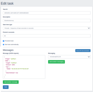
Here you need to set the Start Time type to Periodic and choose a period in second – in my case – every minute.
In the bottom left part, you need to fill in the message you want to send every minute into your IQRF network. It is in JSON format.
The message I am sending can be found here – json_request_scheduler.txt. What is the most important thing here is this line:
"rData": "00.00.0D.00.FF.FF.80.00.00" = this line is the command you will be sending into the IQRF network, and you can notice that this line is identical to the line I sent when I was testing IQRF network with the IQRF IDE. This line targets all nodes (FF.FF) and reads the temperature (80.00.00).
Next you need to choose what MQTT messager you want to use – choose the one you created earlier.
Now you should have your IQRF Daemon working and sending commands into your network every minute. Responses that your coordinator gets are then sent using the MQTT protocol.
Step 7: Implement code for receiving MQTT messages and sending them using serial interface
I wrote this code in Python. The Raspberry Pi should be able to run Python codes from the start, if it does not, you may need to install it.
The whole code can be found here – rpi_code.py
import paho.mqtt.client as mqtt
import serial
These two lines import mqtt client and serial interface that is needed for sending data to the Adafruit Feather 32u4.
numberOfNodes=2
tmp=0

ser = serial.Serial("/dev/ttyACM0", 9600, timeout=1)
ser.reset_input_buffer()
numberOfNodes is the number of nodes in your network. If your network changes or if you expand it at any time, you need to change the number here also.
Next, you initialize the serial interface – /dev/ttyACM0 is the port my Adafruit Feather 32u4 uses, and 9600 is the baud rate.
IMPORTANT: Your port name may be different.
The easiest way to find out what port is yours – unplug your Adafruit Feather 32u4 from your Raspberry Pi. Type the command ls /dev/ – this command will show you what devices/interface there are. Then connect the Adafruit Feather 32u4 and Raspberry Pi via USB cable and run that command again. There will be a new port/interface listed – that is your port name.
Then these lines are used for initializing the MQTT client:
client = mqtt.Client()
client.on_connect = on_connect
client.on_pre_connect = None
client.on_message = on_message
client.connect("127.0.0.1", 1883, 60)
client.loop_forever()
The first line creates new Client called client, next three lines define what to do when your client connects and what to do when it receives the message. Then there is the connection itself – you need to type the same broker name you used in your IQRF Daemon MQTT setup and that same port. The last line says that the code will be running and listening for any new messages.
The next line you may need to change is the line in def on_connect(client, userdata, flags, rc) function:
client.subscribe("Iqrf/DpaResponse1") – this line says which topics your MQTT client will be subscribing to. This needs to be the same topic your IQRF Daemon is publishing to.
Now, before explaining the last part of the code, response from your IQRF network also comes in JSON format, just like the request is. It looks like this:
{
"mType": "iqrfRaw",
"data": {
"msgId": "testRaw",
"timeout": 1000,
"rsp": {
"rData": "00.00.0d.80.00.00.00.00.03.00.19.18.00.00.00.00.00.00.00.00.00.00.00.00.00.00.00.00.00.00.00.00.00.00.00.00.00.00.00.00.00.00.00.00.00.00.00.00.00.00.00.00.00"
},
"raw": [ {
"request": "00.00.0d.00.ff.ff.80.00.00",
"requestTs": "2023-04-18T22:41:48.078+01:00",
"confirmation": "",
"confirmationTs": "",
"response": "00.00.0d.80.00.00.00.00.03.00.19.18.00.00.00.00.00.00.00.00.00.00.00.00.00.00.00.00.00.00.00.00.00.00.00.00.00.00.00.00.00.00.00.00.00.00.00.00.00.00.00.00.00",
"responseTs": "2023-04-18T22:41:48.644+01:00"
} ],
"insId": "iqrfgd2-default",
"statusStr": "ok",
"status": 0
}
}
In the request section, there is the command IQRF Daemon sent into the network. In the section rData there is the answer from nodes.
So given the response: 00.00.0d.80.00.00.00.00.03.00.19.18.00.00.00..... = these are all hexadecimal values, data starts with the 11th value – 19.18.00.00.00….
So the first node responded 19, the second node responded 18, third node responded 00 (because there is no third node in my network) and so on.
The last part of the code is this:
def on_message(client, userdata, msg):
tmp=0
finalString = ""
temp = msg.payload.decode("utf-8")
sepBeginning = '"rData": "'
strippedBeginning = temp.split(sepBeginning, 1)[1]
sepEnd = '"'
strippedEnd = strippedBeginning.split(sepEnd,1) [0]
temperatureFromAllNodesString = strippedEnd[30:]
temperatureFromAllNodesList = Convert(temperatureFromAllNodesString)

for node in temperatureFromAllNodesList:
temperature = intoDecimal(node)
finalString += str(temperature)
finalString += "."
tmp=tmp+1
if tmp==numberOfNodes:
break

print(finalString)
ser.write(finalString.encode('utf-8'))
When a message arrives from the MQTT protocol, it is saved in a variable temp.
Then the message is filtered and stripped – it saves only the answers from nodes into the temperatureFromAllNodesString variable, and then it converts it into a list so it is easier to work with.
So when the message arrives, it converts the whole answer 00.00.0d.80.00.00.00.00.03.00.19.18.00.00… into 19.18.00.00… and it gets saved into the list.
Loop for node in temperatureFromAllNodesList then converts the temperatures one by one into decimal numbers and it saves the results in finalString, adding the “.” symbol between every value.
The final line of the code means that that finalString gets written on the serial.
You can then run the code by this command:
python3 your_code_name.py
B) Adafruit Feather 32u4
Step 1: Get Adafruit Feather 32u4 up and running
Follow the instructions here – download the Arduino IDE, create an account in The Things Network, create your application, and implement Hello Lora! code.
Step 2: Change some settings
If you made the Adafruit Feather 32u4 work and successfully sent Hello Lora! messages to The Things Stack application – you can now be sure you have your Adafruit Feather 32u4 plugged in and wired properly, and you can now proceed and change some configuration.
First, go to The Things Stack application and click Payload Formatters – Uplink. Here, delete the Custom Javascript Formatter you previously pasted and choose CayenneLPP as Formatter Type.
CayenneLPP is a data format for sending data over LoRaWAN network and it is more than suitable for sending sensor data.
Second thing is to upload new code into your Adafruit Feather 32u4. You can find this code here – adafruit_code.ino
This code is essentially the same as your previous code, but it has some small changes:
#include <CayenneLPP.h>
CayenneLPP lpp(51);
Here we the include CayenneLPP library for working with the CayenneLPP data format.
IMPORTANT: Don’t forget to change NWKSKEY, APPSKEY and DEVADDR to the values of YOUR application.
Then this part of the code is essential:
void do_send(osjob_t* j){

temperature = Serial.readString();
firstDot = temperature.indexOf(".");
firstStart = 0;

lpp.reset();
for (int node=0;node<count_dots(temperature);node++) {

lpp.addTemperature(node+1, temperature.substring(firstStart,firstDot).toInt());
firstStart = firstDot+1;
firstDot = temperature.indexOf(".", firstDot+1);
}
LMIC_setTxData2(1, lpp.getBuffer(), lpp.getSize(), 0); // Prepare upstream data transmission at the next possible time
}
The code reads values from the serial interface (the module is connected via USB), and data are saved in a temperature string.
The string looks like this: 25.23. (two nodes in IQRF network, first with a temperature of 25°C, second with a temperature of 23°C).
Then there is a loop for (int node=0;node<count_dots(temperature);node++) – this loop counts dots in the string (2 dots in my example) and therefore counts the number of nodes. Then the value is read and saved into lpp by lpp.addTemperature(channel_number, value). The result after the loop is that the lpp has value 25 stored in channel 1 and value 23 stored in channel 2.
The last line, LMIC_setTxData2 then sends the data over into The Things Stack.
C) Visualize data
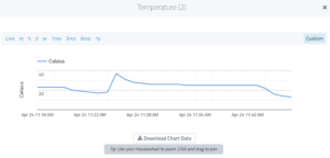
You should see this output in your TTS web console. Click Live Data, and here it is:
Now the last thing is to visualize these data. You can use many methods, like storing values in your own database and then visualizing them using Grafana or some other software. The easiest method is using CayenneLPP, specifically MyDevices website. This website can be used to visualize data that comes in CayenneLPP format in The Things Stack web console.
You can use this tutorial if you want to – it is explained step by step.
You can view the data that came in, you can specify the time and so on.
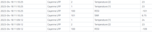
And you can also view graphs, also specified by time.
Changes in your network:
If you ever need to expand your IQRF network, don’t forget to change the numberOfNodes variable in the Raspberry Pi’s code.
If you ever need to read other (sensor) data from the IQRF network, you may need to change the request in MQTT Scheduler to the corresponding command and also change the LPP format in the code uploaded to Adafruit Feather 32u4 (for example change it from the temperature to the humidity)
More information about temperatures and how it is represented can be found here and here.
2b. Solution with two-way communication
This solution is for sending data in a transparent and universal format and for two-way communication. There are no periodically sent messages to the IQRF network. Instead, requests for the IQRF network need to be sent from the LoRaWAN network. The user needs to put the desired request as downlink data, which is sent to the LoRaWAN network as the uplink comes in. That request is then sent to the IQRF network, and the response is sent back to the LoRaWAN network. This is suitable when you have your IQRF network and need to control it from the outside. Unlike the first solution, this one provides data in original hexadecimal format, so you can read how many nodes are there in your network, what request was sent, and what the answer to that request was. This solution can be used, for example, for turning IQRF node LED lights on or off, for reading temperatures, etc.
A) Raspberry Pi
Step 1 to Step 5 is the same as in the previous solution. However, when proceeding with Step 2, make sure you enable SPI interface but disable login-shell.
Step 6: Configure IQRF Daemon
Check the SPI interface as in the previous solution. For this design, I chose to use the default localhost MQTT instance. I just adjusted the topics for requests and responses to be Iqrf/DpaRequest1 and Iqrf/DpaResponse1.
Next, disable the IQRF Scheduler. In this solution, the scheduler is not needed since the user will be sending requests on his own.
Step 7: Implement code for receiving MQTT messages and sending them using the serial interface
I wrote this code in Python. The Raspberry Pi should be able to run Python codes from the start, if it does not, you may need to install it.
The whole code can be found here – rpi_code_both_ways.py.
import paho.mqtt.client as mqtt
import serial
import time
import json
These lines implement paho.mqtt broker, enable serial communication, include functions working with time and JSON format.
noOfNodes=0
tmp=0

ser = serial.Serial("/dev/ttyACM0", 9600, timeout=1)
ser.reset_input_buffer()
These lines are the same as in the previous solution, but here the noOfNodes is not the value that you need to set. In this solution, the number of IQRF nodes is automatically discovered when starting the script.
def on_connect(client, userdata, flags, rc):
    if rc == 0:
      print("MQTT Connection OK.")
    else:
      print(f"Connected fail with code {rc}")
      client.subscribe("Iqrf/DpaResponse1")
      jsonrequest=json.dumps({"mType": "iqrfRaw","data": {"msgId": "testRaw","timeout": 1000,"req": {"rData": "00.00.00.00.FF.FF"}}})
      client.publish("Iqrf/DpaRequest1",jsonrequest)
In the method on_connect() is the subscribed topic for responses, and as the MQTT client connects, there is a message sent to the IQRF network. The message discovers how many nodes there are in the network. The request is published in the topic Iqrf/DpaRequest1 and the response is then published in the Iqrf/DpaResponse1 topic. Remember, this only happens when the MQTT client connects (at the start of the script).
def on_message(client, userdata, msg):
   global tmp
   global noOfNodes
   if tmp==0:
     noOfNodes = intoDecimal(((msg.payload.decode("utf-8").split('"rData": "',1)[1]).split('"',1)[0])[24:26])
     print("Number of nodes in IQRF network is",noOfNodes)
     tmp=1
   else:
     mqttmessage = msg.payload.decode("utf-8")
     request=(mqttmessage.split('"request": "',1)[1]).split('"',1)[0]
     response=(mqttmessage.split('"response": "',1)[1]).split('"',1)[0]
     segments = response.split(".")
     for i in range(len(segments) - 1, -1, -1):
         if segments[i] != "00":
             break
     short_response = ".".join(segments[:i+1])
     finalMessage =str(noOfNodes)+("_")+request+("_")+ short_response
     print ("Data from IQRF network:")
     print (finalMessage)
     ser.write(finalMessage.encode('utf-8'))
In the method on_message(), the IF/ELSE condition is for distinguishing whether the response in topic Iqrf/DpaResponse1 is response regarding the number of nodes in the IQRF network or whether the response is a typical response carrying data that needs to be sent. Only the first message that is received after running the script is the response about how many nodes there are. In that case, the number of nodes is saved as the value noOfNodes. Every next response is a message carrying data. In this case, the message is split into the request and response parts. Then, the finalMessage is composed of numberOfNodes_request_response. So this is the fixed format, which can look like this:
2_ 00.00.0D.00.FF.FF.80.00.00_ 00.00.0d.80.00.00.00.66.08.00.17.18
The message above means that there are 2 nodes in the network, the request that came is 00.00.0D.00.FF.FF.80.00.00, and the response to this request is 00.00.0d.80.00.00.00.66.08.00.17.18. When this message is then received in the LoRaWAN end application, user can work with these three values.
The FOR condition is for removing redundant zeros from the end of the answer.
Next, at the end of the script, there is a While condition that runs indefinitely.
while (True):
	client.loop(.1)
	if(ser.inWaiting()>0):
		data_str = ser.readline(ser.inWaiting()).decode('ascii')
		if (data_str.startswith("requestlora_")):
			data_str = data_str.replace("requestlora_","")
			tmprequest1 = '{"mType": "iqrfRaw", "data": {"msgId": "testRaw", "timeout": 1000, "req": {"rData": "'
			tmprequest2 ='"},"returnVerbose": true}}'
			tmprequest = tmprequest1 + data_str.strip() + tmprequest2
			client.publish("Iqrf/DpaRequest1",tmprequest)
		else:
			print(data_str)
This part of the code listens to the serial interface for any messages that are sent from the LoRa module. If the message starts with “requestlora_”, it indicates that the message contains data from the LoRaWAN network that needs to be sent to the IQRF network. If this kind of message is detected, it is published in the Iqrf/DpaRequest1 topic and sent into the IQRF network. The IQRF network then answers this request, and the answer is sent back to the LoRa module for uplink transmission.
B) Adafruit Feather 32u4
Step 1: Get Adafruit Feather 32u4 up and running
Follow the instructions here – download the Arduino IDE, create an account in The Things Network, create your application, and implement Hello Lora! code.
Step 2: Change some settings
If you made the Adafruit Feather 32u4 work and successfully sent Hello Lora! messages to The Things Stack application – you can now be sure you have your Adafruit Feather 32u4 plugged in and wired properly, and you can now proceed and change some configuration.
First, go to The Things Stack application and click Payload Formatters – Uplink. Here, delete the Custom Javascript Formatter you previously pasted and paste this one:
function Decoder(bytes, port) {
  var parts = String.fromCharCode.apply(null, bytes).split('_');

  var part1 = parts[0];
  var part2 = parts[1];
  var part3 = parts[2];

   return {
    numberOfNodes: part1,
    request: part2,
    response: part3
  };
}
This formatter splits the message it receives into three parts – number of nodes, request, and a response. It can be found here – payload_formatter_both_ways.txt.
The second thing is to upload new code into your Adafruit Feather 32u4. You can find this code here – adafruit_code_both_ways.ino.
IMPORTANT: Don’t forget to change NWKSKEY, APPSKEY and DEVADDR to the values of YOUR application.
Before explaining the code, please note this. Because Adafruit Feather 32u4 is a LoRa device supporting only class A (receiving downlink messages only after sending uplinks), I needed to send uplinks periodically to make sure that when the user inputs the request as a downlink message, it gets to the LoRa end device. So the variable const unsigned TX_INTERVAL = 60 means that the LoRa device will send an uplink every 60 seconds. Please change this variable based on how often you need to receive downlinks. If you only want to send IQRF requests a few times a day, the interval might be 60 minutes or more.
This periodic sending is there only because of class A restrictions. If you are using the LoRa module, which works with class B or class C, these periodic uplinks are not needed. I chose an interval of 1 minute for testing purpose. Since most of the time there is no data to be sent, the uplinks will contain “0_0_0”.
The code for sending uplinks looks like this:
void do_send(osjob_t* j){
    if (Serial.available() > 0) {
      String mojedatastring = Serial.readString();
      Serial.print("Found request from IQRF network sent via Serial that looks like this:");
      Serial.println(mojedatastring);
      LMIC_setTxData2(1, mojedatastring.c_str(), strlen(mojedatastring.c_str()), 0);    // Prepare upstream data transmission at the next possible time.
      Serial.println("Serial data sent from IQRF to LoRa network.");
      Serial.flush();
      mojedatastring = "";
    }
    else {
      String mojedatastring = "0_0_0";
      LMIC_setTxData2(1, mojedatastring.c_str(), strlen(mojedatastring.c_str()), 0);    // Prepare upstream data transmission at the next possible time.
      Serial.print("No serial data found from IQRF network, sending zeros to LoRa to keep class A working.");
      mojedatastring = "";
    }
}
If there is a serial message available from the IQRF network, it will be sent to the LoRaWAN network. If there is no message available each minute, “0_0_0” will be sent to the LoRaWAN network. After sending the uplink, there will be two windows opened for receiving the downlink:
void onEvent (ev_t ev) {
    if(ev == EV_TXCOMPLETE) {
      Serial.println(F("LoRa TX done."));
      if (LMIC.txrxFlags & TXRX_ACK)
        Serial.println(F("Received ack."));
      if (LMIC.dataLen) {
        Serial.print(F("Received "));
        Serial.print(LMIC.dataLen);
        Serial.println(F(" bytes of payload from LoRa network."));
        requestStr = "";

        for (int i = LMIC.dataBeg; i < LMIC.dataBeg+LMIC.dataLen; i++) {
          myNewHex2(LMIC.frame[i], i, LMIC.dataBeg+LMIC.dataLen);

        }

        Serial.println("requestlora_" + requestStr);
        requestStr = "";

      }
      os_setTimedCallback(&sendjob, os_getTime()+sec2osticks(TX_INTERVAL), do_send);  // Schedule next transmission
    }
}
If there is a planned downlink, the LoRa module will receive it, and then the code adds the “requestlora_” prefix to the message. The message is then sent to the Raspberry Pi, the prefix is detected, the message is parsed into JSON request format, and sent to the IQRF network.
Now that Adafruit and the Raspberry Pi are both configured, it is time to run the code and plug in the Adafruit Feather 32u4.
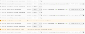
You can run the Python code using python3 nameofcode.py. You should see the following output in the terminal:
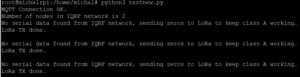
The code tells you how many nodes you have in your IQRF network, and then each minute (TX interval) it says that no serial data was found from the IQRF network and that it is sending zeros to keep class A working. In the TTS console, you should see the following:
This output means that the zeros were sent into the LoRaWAN network. Now, until the user inputs a downlink message with a request for the IQRF network, the zeros will keep sending every minute. Go to the TTS console, click Messaging->Downlink, and input the Payload tab. Note that this is not the only way to send downlinks to LoRa end nodes, you can find many tutorials and manuals online about how to create your own code or application and send downlinks that way.
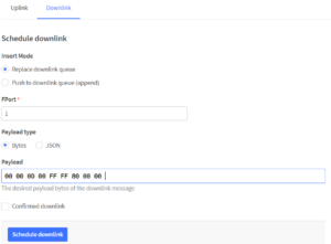
You can fill in any command you want, I chose this one to read the temperatures. Other example is command for turning the LED light on (00.00.0D.02.FF.FF.02.3E.00.00.00.00.00.00.00.00.00.00.00.00.00.00.00.00.00.00.00.00.00.00.00.00.00.00.00.00.00.05.06.01.FF.FF) or turning them back off (00.00.0D.02.FF.FF.02.3E.00.00.00.00.00.00.00.00.00.00.00.00.00.00.00.00.00.00.00.00.00.00.00.00.00.00.00.00.00.05.06.00.FF.FF).
After you press the Schedule Downlink button, you should see the following in the TTS console:
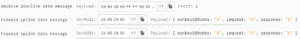
This means that your downlink is planned and will be sent after the next uplink. After the next uplink, you should see the following in your Raspberry Pi terminal:
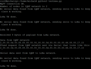
The output says that LoRa transmission was done (uplink was sent) and that it received 9 bytes of payload from the LoRaWAN network. The data received was then sent through the serial interface into the Raspberry Pi, message was formatted in JSON format and sent as a request into the IQRF network. The IQRF network answered this request, and Raspberry Pi´s code processed that as 2_00.00.0d.00.ff.ff.80.00.00_00.00.0d.80.00.00.00.66.08.00.17.15.
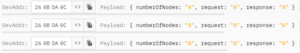
So now that message is sent to the LoRa module and sent as the next uplink into the LoRaWAN network. In the TTS console, you should see this after the next uplink:
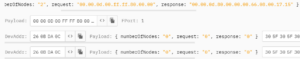
This solution is more versatile as it sends the data both ways and allows the data to be transparent in its original hexadecimal format. It is up to the user to process these data and create an application that works with them.
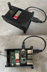
3. Build a case for your gateway
Now that your device is working, you can make a case so it is in one piece and protected.
I designed a 3D printed box for the Raspberry Pi, IQRF module, and Adafruit Feather 32u4 with an antenna on the outside.
You can find the .stl files for 3D printing here – spodnicast.stl (case) and vrchnicast.stl (lid).
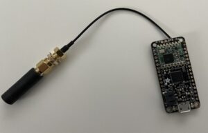
For the case to be suitable for this solution, you need an antenna that is connected to the Adafruit Feather 32u4 with a small cable.
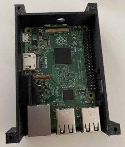
First, insert your Raspberry Pi into the case:
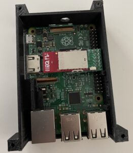
Next, connect your IQRF transceiver and KON-RASP-01 adapter to the right pins:
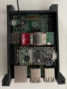
Then put your Adafruit Feather 32u4 between the IQRF module and USB ports of the Raspberry Pi like this:
Next, you need to drill a small hole for the antenna (not present in the 3D model), and your device should look like this: