
| TTN version: | TTNv3 |
| Activation: | ABP |
| Device Class: | Class A |
| Last updated: | August 1, 2025 |
This article provides instructions for making a GPS tracker using Adafruit Feather M0 RFM96 LoRa Radio and NEO-6M. If you haven’t set up Adafruit Feather M0 yet, check out our 433 MHz Adafruit Feather M0 tutorial.
You can use this tracker for tracking for example your bike or suitcase. The tracker can run on battery power or can be powered from USB. This device can be also used as TTN mapper to map The Things Network coverage. Learn more about using the GPS Tracker as a TTN Mapper.
Prepare
- Adafruit Feather M0 RFM96 LoRa Radio (Adafruit 3179)
- GPS module with NEO-6M (GY-NEO6MV2)
- LiPoly 3,7 V battery (1200 mAh or more)
- Switch ON-OFF-ON 6 pins (MTS-203 )
- LED green/red (L-59EGW)
- Male U.FL connector (for Adafruit Feather M0)
- pigtail U.FL – SMA Female
- pigtail U.FL – RP-SMA Female
- LoRa 433 MHz antenna (ANT-433-CW-RAH)
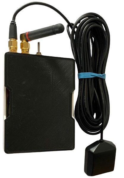
- GNSS antenna (AP‐AGNSS‐SMA‐SC174)
- 13x wire
- Box (3D model)
- 4x screw
- PC + micro USB cable
When using the 3,7V 1200 mAh battery and SF7, the device lasts 18 hours and send about 2100 messages on a single charge (measured at room temperature 25 °C).
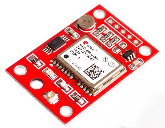
GPS module GY-NEO6MV2
To determine the location, we will use the GPS module GY-NEO6MV2 with NEO-6M. The module requires a stabilized supply voltage in the range of 3.3 V to 5.5 V for its function.
Assembly
Connect everything according to the schematics bellow.
Wire up the Adafruit Feather M0’s IO1 pin with pin 6.
The battery is connected to the two middle pins of the switch. Two left pins with 3,7 V are connected and one of this pins is connected to Feather’s pin BAT. This means that when the switch is in the middle position, the battery is disconnected from Feather, otherwise the battery is connected. Middle pin of switch with battery GND is connected to Feather’s GND. One right pin of switch with GND is connected to Feather’s pin A1. Second right pin of switch with GND is connected to Feather’s pin A0.
LED’s middle pin is connected to 220 Ω resistor that is connected to Feather’s GND pin. LED’s pin with green colour is connected to Feather’s pin A4. LED’s pin with red colour is connected to Feather’s pin A5.
GPS module NEO-6M is connected using four wires. The first GPS module pin GND is connected to ground (GND pin on Feather), second GPS module pin Tx is connected to Feather’s pin Rx, the third GPS module pin Rx is connected to Feather’s pin Tx and the fourth GPS module pin VCC is connected to the supply voltage (3V pin on Feather).
![]()
![]()
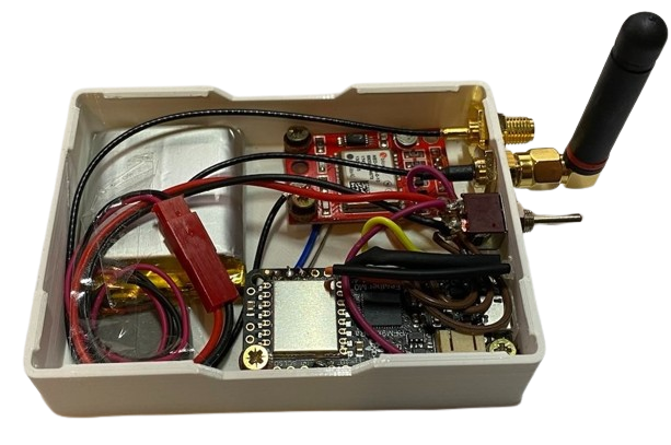
Put everything in a small box and connect pigtail U.FL – SMA Female to GPS module and RP-SMA Female to Adafruit Feather M0. Then screw on the antennas.
Arduino IDE setup
- Run Arduino IDE.
- In the Arduino IDE Library Manager search TinyGPSPlus by Mikal Hart and install it.
- Than in search RTCZero for Real Time Clock Library and install it.
GPS Tracker test
To test your assembled GPS Tracker follow this instructions:
- Copy and paste this program to your Arduino IDE.
- Set the switch on the GPS Tracker to the middle (OFF) position.
- Connect Adafruit Feather M0 using micro USB cable to your computer.
- In Arduino IDE click on Upload button to upload program to your Adafruit Feather M0.
- In Arduino IDE click on Serial Monitor button and you should every second see this:
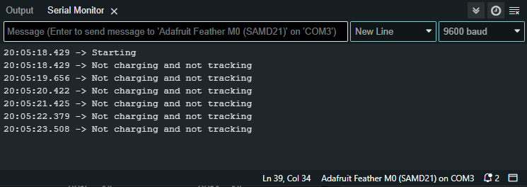
- LED should blink green and red.
- Set the switch on the GPS Tracker to one side (ON) .
- LED should blink green.
- You should see this in Serial Monitor every second:
- Set the switch on the GPS Tracker to the other side (ON) .
- LED should blink red.
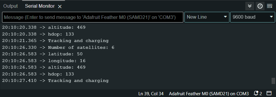
- You should see this in Serial Monitor every second:

Program for sending coordinates to TTS
We have prepared program for sending latitude, longitude, altitude and hdop to TTS every +-30 seconds.
Program and TTS setup
- Copy and paste GPS Tracker program to your Arduino IDE.
- In program replace NWKSKEY, APPSKEY and DEVADDR with keys of your end device registred in TTS. Keys are in TTS -> Applications -> YourAppName -> YourEndDeviceName -> Overview -> Session information.
- In TTS -> Applications -> YourAppName -> Payload formatters -> Uplink change Formatter type to Custom Javascript formatter and to Formatter code copy and paste code bellow:
function decodeUplink(input) { var data = {}; data.latitude = (input.bytes[0] << 16) + (input.bytes[1] << 8) + input.bytes[2]; data.latitude = (data.latitude / 10000) data.longitude = (input.bytes[3] << 16) + (input.bytes[4] << 8) + input.bytes[5]; data.longitude = (data.longitude / 10000) data.altitude = (input.bytes[6] << 8) + input.bytes[7]; data.altitude = data.altitude / 10 data.hdop = input.bytes[8] / 10; return { data: data, warnings: [], errors: [] }; } - Save changes.
- Set the switch on the GPS Tracker to the middle (OFF) position.
- Connect Adafruit Feather M0 using micro USB cable to your computer.
- In Arduino IDE click on Upload button to upload program to your Adafruit Feather M0.
- The LED should start flashing green and red.
- Set the switch on the GPS Tracker to the Tracking position (as shown bellow).
- The LED should start flashing green.
- If the GPS data are valid, then the LED flashes green at a longer interval and the data are sent to the TTS.
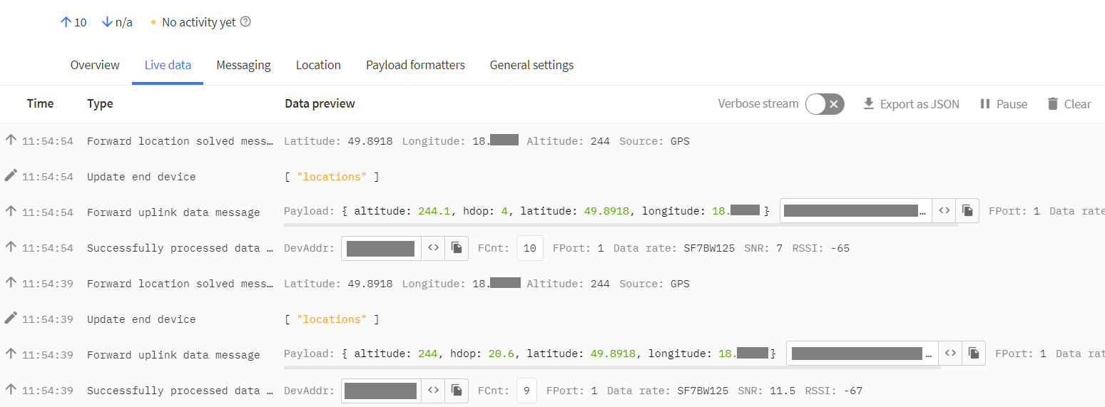
- In TTS -> Applications -> YourAppName -> YourEndDeviceName -> Live data you should every +-30 seconds see this:
Operating modes
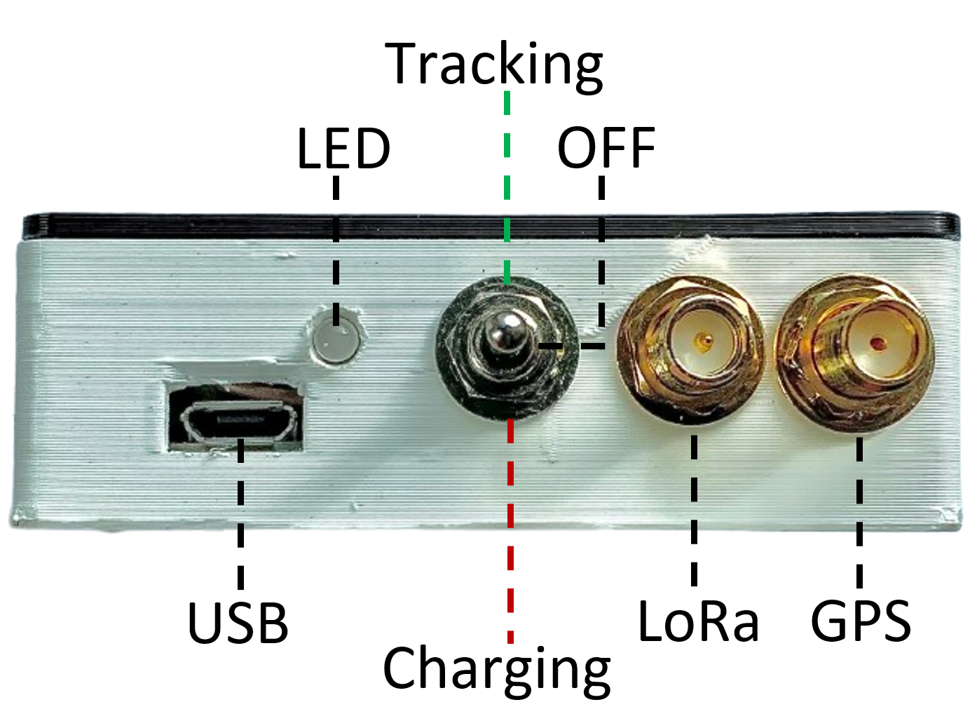
Description of parts
USB power
The following section describes the operating modes of the GPS Tracker when powered from USB:
Charging
- The switch is in the Charging position
- The battery is charging
- The LED flashes red
- The GPS Tracker is not sending data to the TTS
OFF / Program update
- The switch is in the OFF position
- the battery is not charging
- the LED flashes green and red
- the GPS Tracker is not sending data to the TTS
Tracking
- The switch is in the Tracking position
- The battery is charging
- The LED flashes green
- The GPS Tracker sends data to the TTS
If the switch is in the Tracking position and the GPS data are valid, then the LED flashes green at a longer interval and the data are sent to the TTS.
Battery power
The following section describes the operating modes of the GPS Tracker when running on battery power:
Charging – Don’t use this mode!
- The switch is in the Charging position
- The LED flashes red
- The GPS Tracker is not sending data to the TTS
OFF
- The switch is in the OFF position
- The GPS Tracker is OFF
Tracking
- The switch is in the Tracking position
- The LED flashes green
- The GPS Tracker sends data to the TTS
If the switch is in the Tracking position and the GPS data are valid, then the LED flashes green at a longer interval and the data are sent to the TTS.
Program update
- Set the switch on the GPS Tracker to the middle (OFF) position.
- Connect Adafruit Feather M0 using micro USB cable to your computer.
- The LED should start flashing green and red.
- In Arduino IDE click on Upload button to upload program to your Adafruit Feather M0.
- The LED should start flashing green and red.