| TTN version: | TTNv3 / TTSS |
| Board: | LilyGO T-Beam v1.2 |
| Activation: | OTAA |
| Device Class: | Class A |
| Last updated: | April 29, 2026 |
This page was created as part of a bachelor’s thesis by Armin Gembal at VSB – Technical University of Ostrava, with the topic Design and Assembling of the Communication Node of the LoraWAN technology Operating at 433 MHz Band.
This project describes the assembly of a battery-powered alarm device operating on a LoRaWAN network in the 433 MHz frequency band. The key feature of the node is its Deep Sleep operation mode. The device wakes up only when one of the three connected sensors detects an event. After waking up, the ESP32 sends a single-byte packet to TTN (The Things Network). TTSS (The Things Stack Sandbox) then forwards the message via Webhook to GAS (Google Apps Script). The script decodes the payload and immediately sends a text notification to a Telegram chat.
Prepare
- LilyGO T-Beam v1.2 (with SX1268 chip for 433 MHz)
- Motion sensor PIR HC-SR505
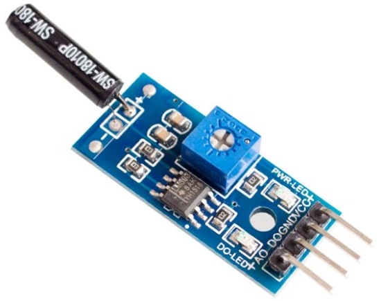
- Vibration sensor SW1801P
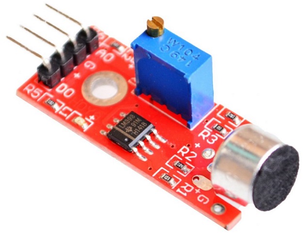
- Sound sensor KY-037
- Li-Ion battery in 18650 format (recommended 3500 mAh)
- 9x Wires
- Breadboard
- Box (3D model)
- Lid (3D model)
- PC + Micro-USB cable
When using the 3500 mAh battery, the device lasts 12 days on a single charge.
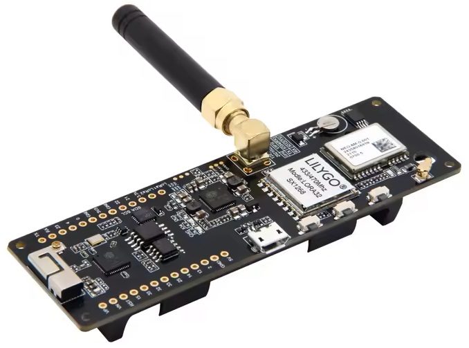
LilyGO T-Beam v1.2
The LilyGO T-Beam v1.2 module is a comprehensive development platform that combines a ESP32 microcontroller, a LoRa SX1268 433 MHz radio module, a u-blox NEO-6M GPS module, and an AXP2101 power management circuit on a single board. Serial communication with a computer is handled by a CH9102F USB-to-UART converter. Unlike simple peripheral LoRa modules, it does not require an external microcontroller. All computing power, radio communication, power management, and GPS are integrated directly on the board.
The board features an ESP32 chip running at 240 MHz with 4 MB Flash and 8 MB PSRAM, integrated Wi-Fi and Bluetooth 4.2. The radio section is handled by a Semtech SX1268 chip with a maximum transmit power of 10 mW (+10 dBm). Power management is provided by the AXP2101 chip, which allows software-controlled disconnection of voltage rails and powers the board from an 18650 Li-Ion battery or via micro-USB.
Detection sensors
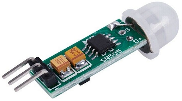
Motion sensor PIR HC-SR505 (GPIO 14) – a passive infrared sensor that detects motion based on changes in infrared radiation in the surrounding environment.
Vibration sensor SW1801P (GPIO 25) – a mechanical sensor sensitive to shocks and vibrations. When a vibration is detected, the digital output switches to logical HIGH. Suitable for detecting impact or movement of an object it is attached to.
Sound sensor KY-037 (GPIO 13) – a microphone with a comparator. The digital output switches to HIGH when the configured volume threshold is exceeded. Sensitivity can be adjusted using the trimmer directly on the module.
Assembly
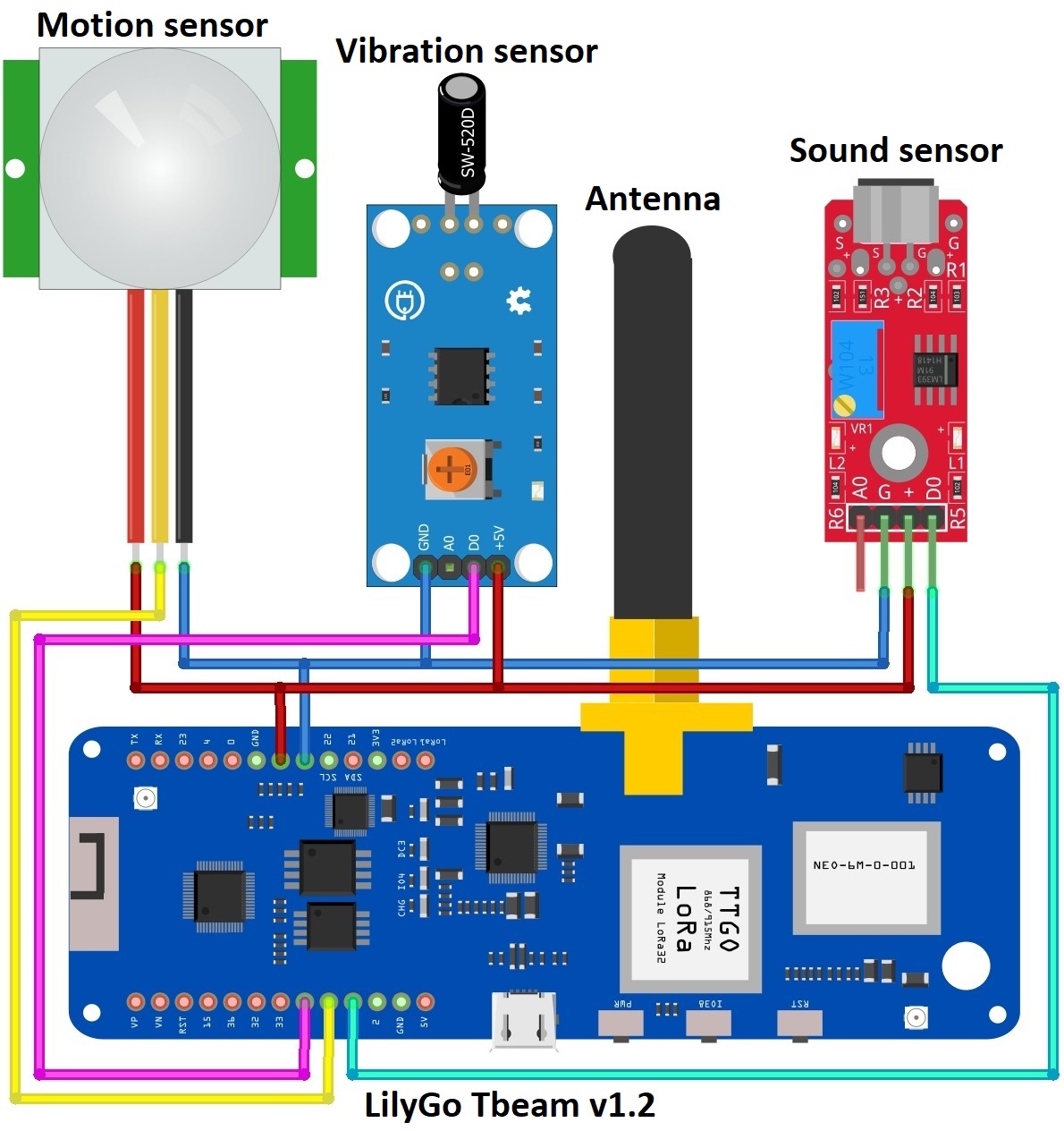
Connect everything according to the schematics below:
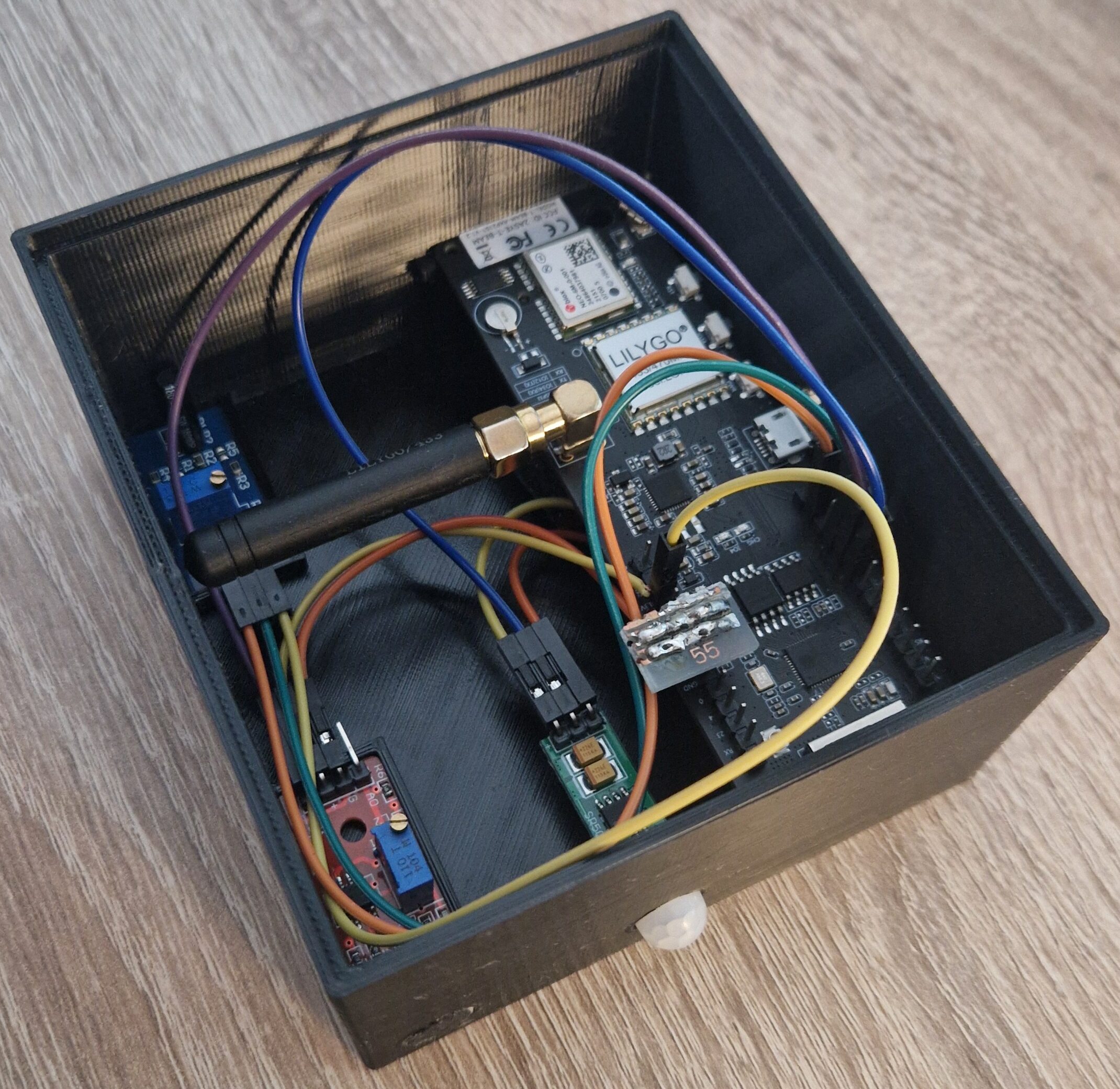
The 18650 Li-Ion battery is connected to the integrated holder on the back of the LilyGO T-Beam board.
The HC-SR505 PIR motion sensor is connected using three wires. The VCC power pin is connected to the 3V3 pin on the LilyGO T-Beam board. The GND pin is connected to the GND pin on the LilyGO T-Beam board. The data pin OUT is connected to pin 14 on the LilyGO T-Beam board.
The SW1801P vibration sensor is connected using three wires. The VCC power pin is connected to the 3V3 pin on the LilyGO T-Beam board. The GND pin is connected to the GND pin on the LilyGO T-Beam board. The data pin DO is connected to pin 25 on the LilyGO T-Beam board.
The KY-037 sound sensor is connected using three wires. The VCC power pin is connected to the 3V3 pin on the LilyGO T-Beam board. The GND pin is connected to the GND pin on the LilyGO T-Beam board. The data pin DO is connected to pin 13 on the LilyGO T-Beam board.
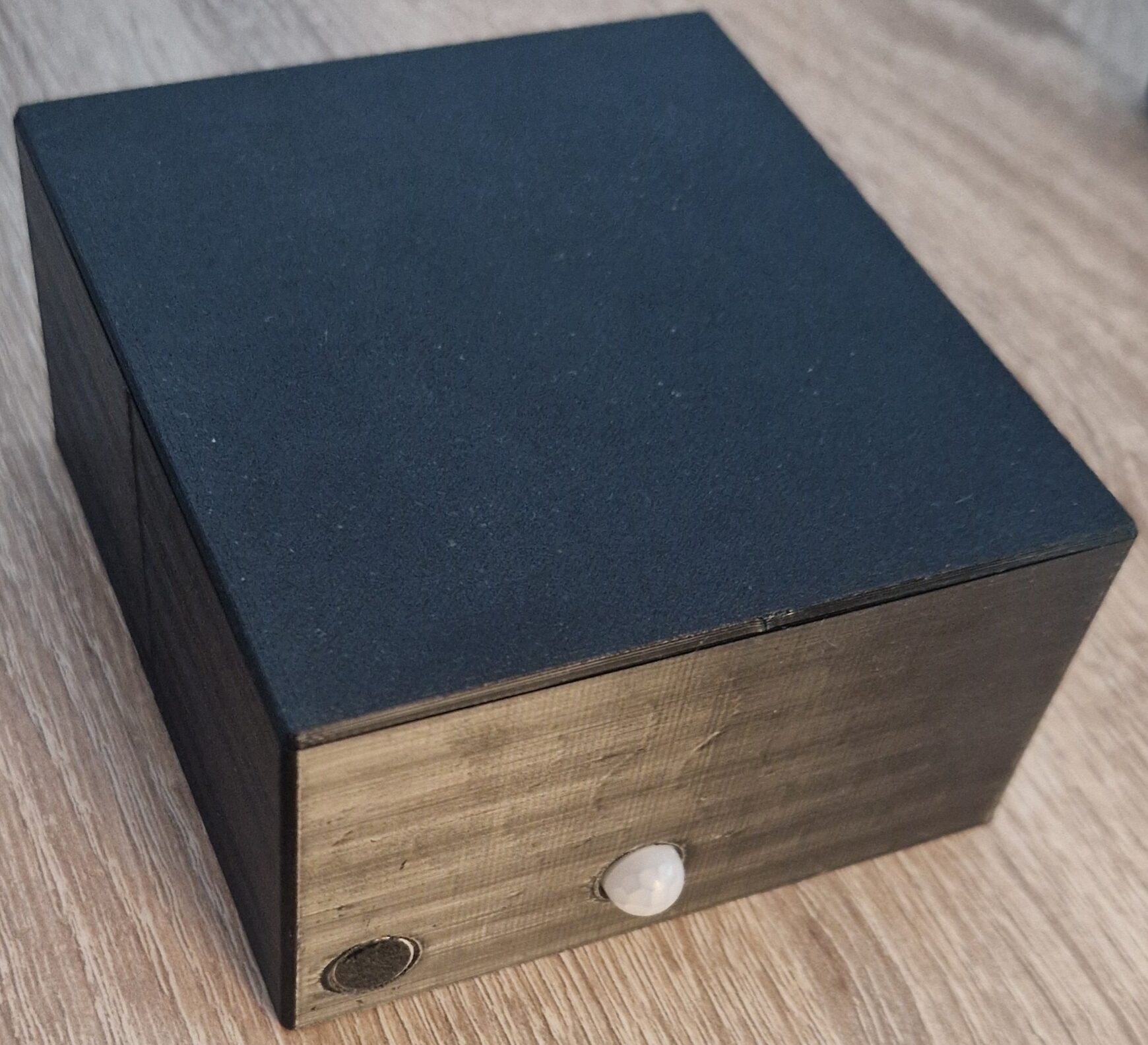
Put everything in a small box.
Arduino IDE setup
- Run Arduino IDE.
- In the Arduino IDE Tools → Board → Boards Manager search esp32 by Espressif Systems and install it.
- In the Arduino IDE Tools → Manage Libraries search MCCI LoRaWAN LMIC Library by Matthijs Kooijman and Thomas Telkamp and install it.
- In the Arduino IDE Tools → Manage Libraries search XPowersLib by Lewis He and install it.
Modifying LMIC library configuration
The default LMIC library configuration assumes use of the 915 MHz band. To operate in Europe on the 433 MHz band, the following modifications are required:
- In the installed library, go to the folder MCCI_LoRaWAN_LMIC_library → src → lmic and place the modified lorabase_eu868.h file there, replacing the existing file with the same name. This file has been specially modified for broadcasting in the 433 MHz frequency band.
- Open the configuration file MCCI_LoRaWAN_LMIC_library → project_config → lmic_project_config.h. Comment out the line
#define CFG_us915 1and uncomment#define CFG_eu868 1. This will make the library work with the modified file for the 433 MHz frequency band when used.
Registration LilyGO T-Beam into TTSS
- Log in on The Things Network. If you don’t have account, create one.
- Click on your username and choose Console.
- Select a network cluster Europe 1.
Add application
- Go to applications.
- Click on button + Add application.
- Write something into Application ID.
- Click on button Create application.
Add end device
- In your application click on button + Register end device.
- Input Method – Choose Enter end device specifics manually.
- Frequency plan – Europe 433 MHz (ITU region 1)
- LoRaWAN version – LoRaWAN Specification 1.0.3
- Click on Show advanced activation, LoRaWAN class and cluster settings
- Activation mode – Over the air activation (OTAA)
- Additional LoRaWAN class capabilities – None (class A only)
- Select – Use network’s default MAC settings
- JoinEUI – 0000000000000000
- Click on Confirm.
- DevEUI – Generate
- AppSKey – Generate
- End device ID – here you can name your device
- After registration – View registered end device
- Click on button Register end device
Uploading firmware to the board
- Copy and paste this program to your Arduino IDE.
- In program find // 2. LORAWAN KEYS FOR OTAA CONNECTION and replace DEVEUI and APPKEY with your keys in TTSS
- Connect the LilyGO T-Beam using micro USB cable to your computer.
- In Arduino IDE Tools → Board → esp32 → ESP32 Dev Module and select the correct COM port.
- In Arduino IDE click on Upload button to upload program to your LilyGO T-Beam.
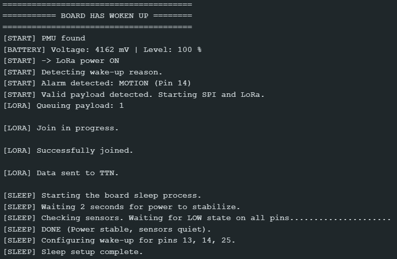
- In Arduino IDE click on Serial Monitor with speed 115200 baud.
- Now in Serial Monitor you can see information from the board. (The board should print information about the wake-up reason, the network join process, and the sleep process.)
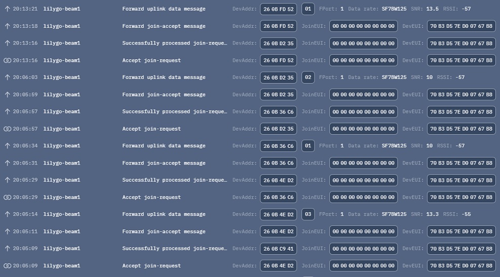
In your TTSS console in Live data you should see incoming messages in real time:
Telegram integration via Google Apps Script
For the device to be truly useful as an alarm, it needs to send notifications to the user. To achieve this, we use a combination of the Telegram Bot API, GAS (Google Apps Script), and the Webhook feature in TTSS.
Create Telegram bot
- Download the Telegram app on your mobile device.
- After logging in, search for the user @BotFather and open a chat with them.
- Send the command /start to begin communication with BotFather.
- Send the command /newbot.
- Enter a display name for your bot (any text).
- Enter a username for your bot (must be unique and end with the word “bot”).
- After successful creation, BotFather will send you the generated TELEGRAM_TOKEN. Save this token — it serves as the password for accessing your bot’s API.
- Open a chat with the newly created bot and send the message /start to activate the chat.
- In a web browser, open the URL https://api.telegram.org/bot00000000000/getUpdates (replace the zeros with your TELEGRAM_TOKEN).
- In the displayed JSON output, find the “chat” and save the value of “id” (this is your CHAT_ID).
Create GAS
- Log in at script.google.com using your Google account.
- Click on New project.
- Copy and paste this program to your GAS.
- In the code, update the TELEGRAM_TOKEN and CHAT_ID variables with your Telegram configuration.
- Click Save project to Drive.
- Then click Deploy → New deployment → select type Web app → set Who has access to Anyone → click Deploy.
- After deployment save displayed Web app URL.
Webhook configuration in TTSS
-
- In your TTSS console, go to the Webhooks tab.
- Click Add webhook and select the type Custom webhook.
- Enter any name in the Webhook ID field.
- Select JSON as the Webhook format.
- Paste the URL of your GAS web app into the Base URL field.
- Enable Uplink message.
- Click Add webhook to save.
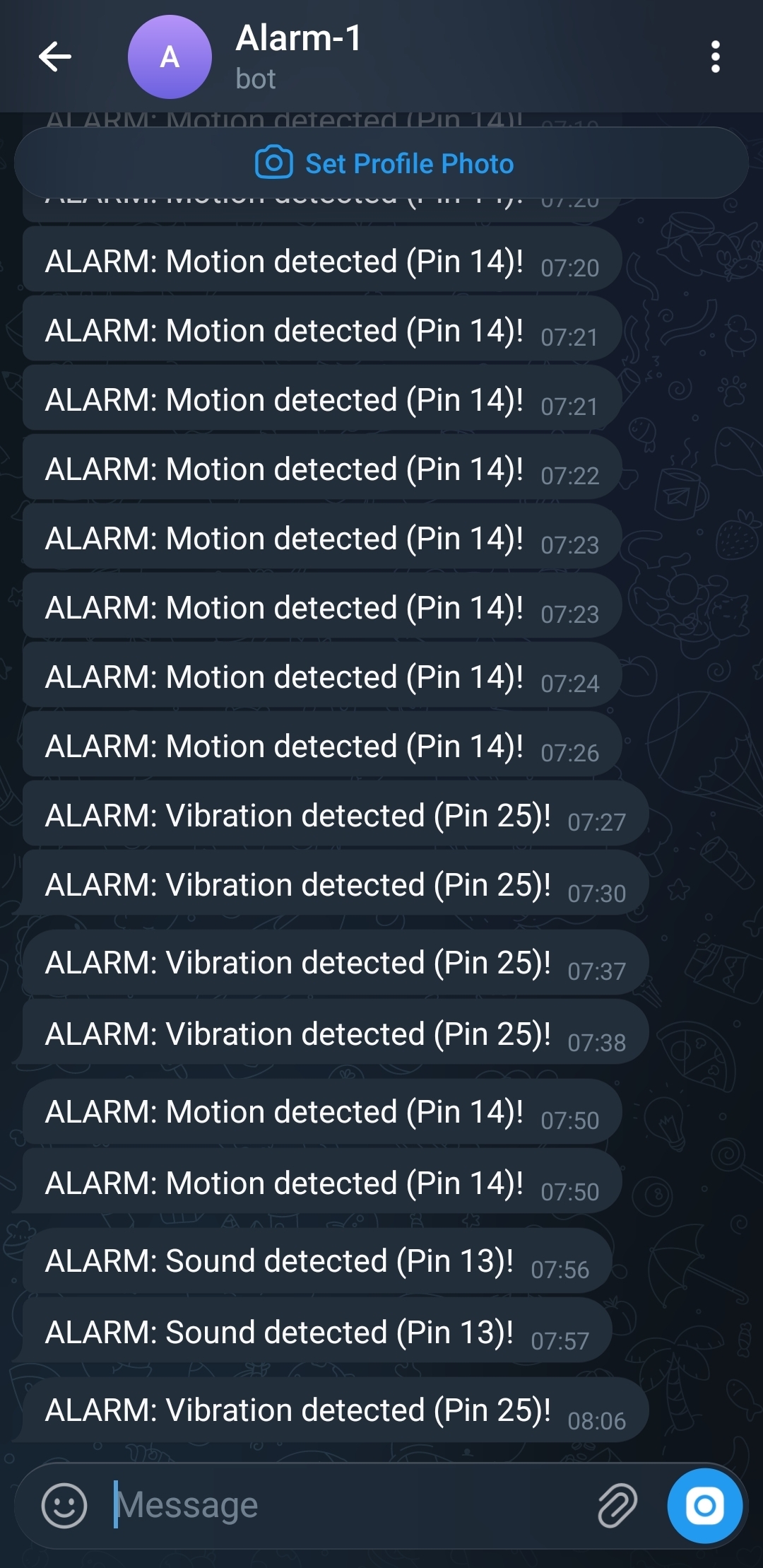
Telegram output
After successfully setting up the entire pipeline, triggering any sensor should cause a notification to appear in your Telegram chat with your bot.