
| TTN version: | TTNv3 / TTS SANDBOX |
| Activation: | ABP |
| Device Class: | Class A |
| Last revision: | April 30, 2026 |
This tutorial demonstrates how to build a complete LoRaWAN 2.4 GHz communication chain consisting of an end node (LilyGO T3 S3) and a gateway (MikroTik wAP LR2), and how to integrate it with The Things Stack Sandbox (TTSS). Unlike standard sub-GHz LoRaWAN, the 2.4 GHz band is globally available without duty cycle restrictions, allowing the same hardware to be deployed worldwide.
The end node uses the Semtech SX1280 transceiver controlled by an ESP32-S3 microcontroller, reads temperature and humidity from a DHT11 sensor, and transmits the values as LoRaWAN uplinks every 15 seconds. Because no public Arduino library supporting the LoRaWAN protocol on the SX1280 transceiver existed at the time of development, a custom LoRaWAN 1.0.2 stack (frame assembly, AES-128 payload encryption, MIC computation) was implemented as part of this project.
Prepare
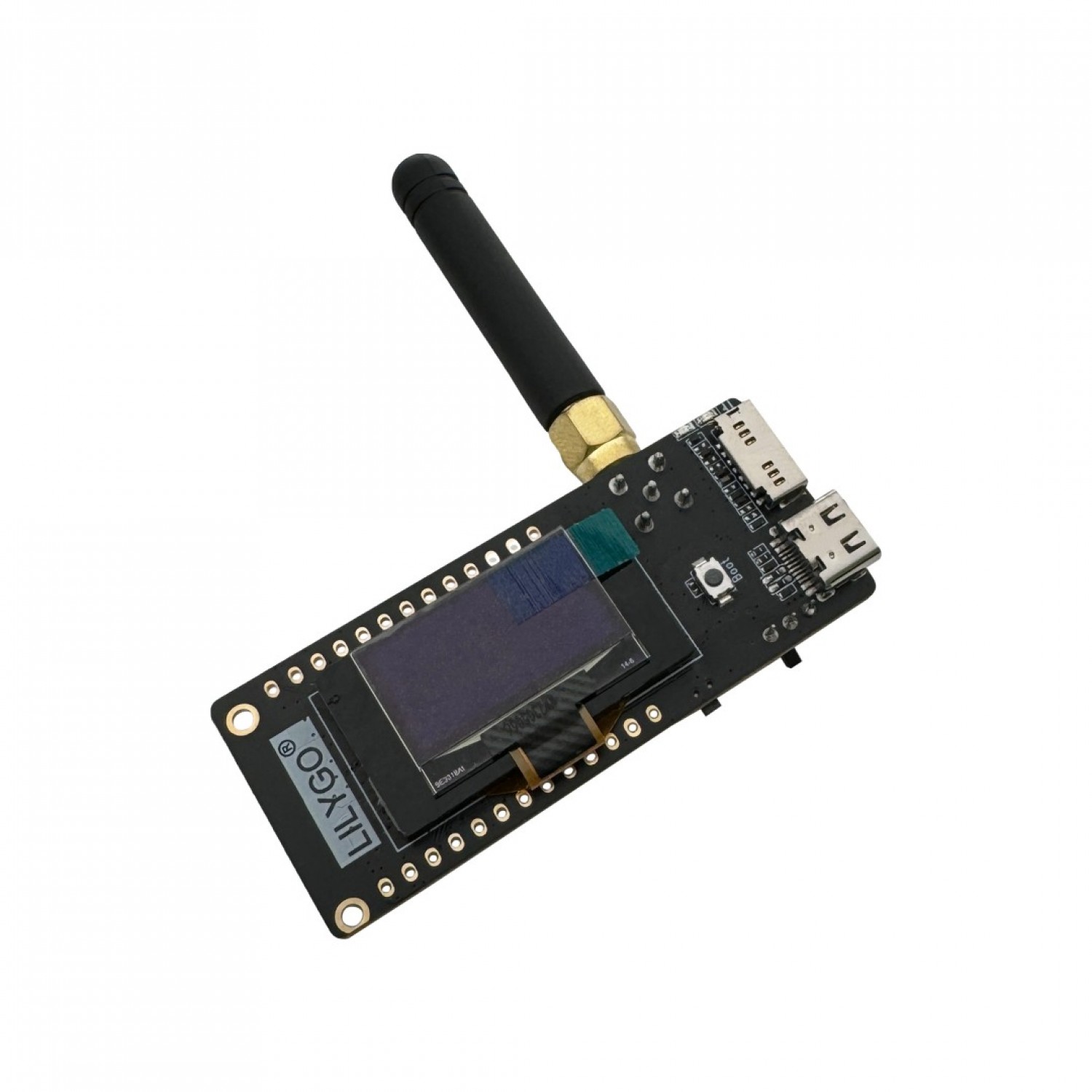
- LilyGO T3 S3 development board (ESP32-S3 + SX1280 with PA, 0.96″ OLED)
- 2.4 GHz antenna (SMA / u.FL)
- MikroTik wAP LR2 gateway (model RBwAPR-2nD&R11e-LR2)
- DHT11 temperature & humidity sensor
- 3x jumper wires (sensor connection)
- breadboard (optional)
- PC + USB-C cable
- Power supply for the gateway
Assembly
Connect the DHT11 sensor to the LilyGO T3 S3 as shown below. The SX1280 transceiver and OLED display are already wired on the development board itself.
| DHT11 Pin | LilyGO T3 S3 Pin |
|---|---|
| VCC | 3V3 |
| DATA | GPIO 15 |
| GND | GND |
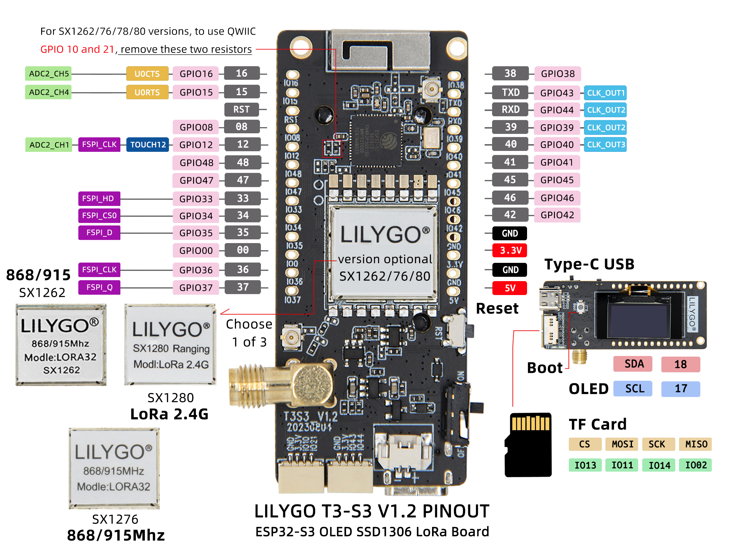
Attach the 2.4 GHz antenna to the SMA / u.FL connector on the LilyGO T3 S3 board before powering it on. Operating the SX1280 transceiver without an antenna may damage the power amplifier.
Gateway setup (MikroTik wAP LR2)
The MikroTik wAP LR2 is a commercial outdoor LoRaWAN gateway running RouterOS, equipped with a miniPCIe R11e-LR2 LoRa card based on the SX1280 chip. Configuration is performed via WinBox.
- Download WinBox from the MikroTik website.
- Power the gateway and connect it to your local network.
- Open WinBox and connect to the gateway (default IP 192.168.88.1, user admin, no password).
- Navigate to the LoRa menu in the left sidebar.
- Open the Servers tab and add a new server pointing to TTSS:
- Name: TTN V3 (eu1)
- Address: eu1.cloud.thethings.network
- UP Port: 1700
- DOWN Port: 1700
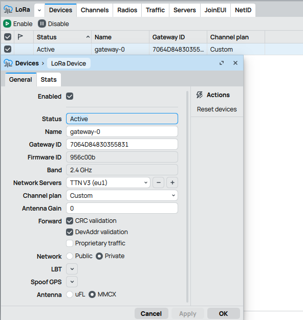
- Open the Devices tab and edit the existing gateway entry:
- Name: gateway-0 (or any identifier)
- Network Servers: TTN V3 (eu1)
- Channel plan: Custom
- Network: Private
- Forward: enable CRC validation and DevAddr validation
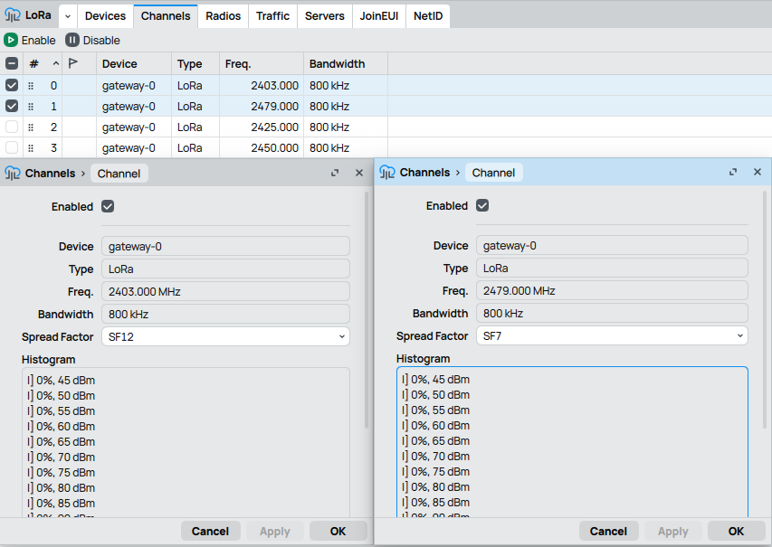
- Open the Channels tab and configure two LoRa channels:
- Channel 0: Freq 2403 MHz, Bandwidth 800 kHz, Spread Factor SF12 (default LoRaWAN 2.4 GHz channel)
- Channel 1: Freq 2479 MHz, Bandwidth 800 kHz, Spread Factor SF7 (used by the end node in this tutorial)
- Make sure both channels are Enabled.
- Note down the Gateway ID shown on the device entry — you will need it when registering the gateway in TTSS.
The frequency 2479 MHz was chosen above the standard Wi-Fi channels 1–13 (2412–2472 MHz) to minimize interference. This frequency also matches one of the three default channels defined by the LoRaWAN 2.4 GHz specification.
Arduino IDE setup
- Download Arduino IDE (version 2.x recommended).
- Run Arduino IDE.
- In the Arduino IDE go to File -> Preferences and copy the link below into the Additional Boards Manager URLs:
https://raw.githubusercontent.com/espressif/arduino-esp32/gh-pages/package_esp32_index.json - Click OK.
- Install the ESP32 boards via Tools -> Board -> Boards Manager -> search esp32 by Espressif Systems -> Install.
- Select Tools -> Board -> ESP32 Arduino -> ESP32S3 Dev Module.
- Set the following options under Tools:
- CPU Frequency: 240 MHz
- USB CDC On Boot: Enabled
- Upload Mode: USB-OTG CDC (TinyUSB)
- Install the required libraries via Tools -> Manage Libraries:
- Adafruit GFX Library
- Adafruit SSD1306
- DHT sensor library by Adafruit
- Connect the LilyGO T3 S3 using a USB-C cable to your computer.
- Choose the appropriate COM port under Tools -> Port.
Activation
Activation By Personalization (ABP) requires hardcoding the device address as well as the security keys (NwkSKey, AppSKey) in the device. ABP is less secure than OTAA, but is used in this tutorial because the custom 2.4 GHz LoRaWAN stack does not implement the OTAA join procedure.
See the documentation for more information on activation.
Activation By Personalization (ABP)
Custom LoRaWAN 2.4 GHz library setup
- Download the source code from the project’s GitHub repository: LoRaWAN-2G4-Node (clone or download as ZIP).
- Place the entire LoRaWAN-2G4-Node folder into your Arduino sketchbook directory (typically Documents/Arduino/).
- Open the LoRaWAN-SX1280.ino sketch in Arduino IDE. The supporting source files (sx1280.cpp, sx1280-hal.cpp, config.cpp, radio.h, etc.) will load automatically as additional tabs.
The custom stack is based on the Sx1280-LoRaWAN-Test-App by MultiTech Systems, which was originally written for Mbed OS and has been ported to Arduino/ESP32, extended with a complete LoRaWAN 1.0.2 frame assembly (AES-128 CTR payload encryption, AES-CMAC MIC computation), DHT11 sensor support, and OLED display feedback.
Add the gateway and end node into The Things Stack
- Create an account on The Things Network if you don’t have one.
- Login on The Things Network.
- Click on your username and choose Console.
- Select the Europe 1 (eu1) cluster.
Add gateway
- Go to Gateways.
- Click on + Register gateway.
- Gateway EUI: enter the Gateway ID from your MikroTik device (16 hex characters).
- Frequency plan: 2.4 GHz with 3 channels (Draft 2)
- Click on Register gateway.
- After a few seconds the gateway status should change to Connected.
Add application
- Go to Applications.
- Click on button + Add application.
- Write something into Application ID.
- Click on button Create application.
Add end device
- In your application click on button + Register end device.
- Input Method – choose Enter end device specifics manually.
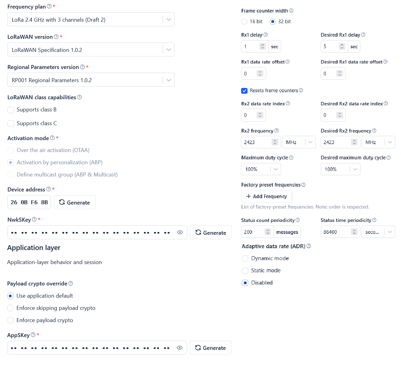
- Frequency plan: LoRa 2.4 GHz with 3 channels (Draft 2)
- LoRaWAN version: LoRaWAN Specification 1.0.2
- Regional Parameters version: RP001 Regional Parameters 1.0.2
- Click on Show advanced activation, LoRaWAN class and cluster settings
- Activation mode: Activation by personalization (ABP)
- Additional LoRaWAN class capabilities: None (class A only)
- Device address: Generate
- AppSKey: Generate
- NwkSKey: Generate
- End device ID: name your device.
- Resets frame counters: Enabled
- Click on button Register end device.
Sending sensor data to TTS
- In TTS -> Applications -> YourAppName -> YourEndDeviceName -> Payload formatters -> Uplink change Formatter type to Custom Javascript formatter and copy the code below into Formatter code:
function decodeUplink(input) { var bytes = input.bytes; var data = {}; if (bytes.length < 4) { return { errors: ["Invalid payload length"] }; } var tempInt = (bytes[0] << 8) | bytes[1]; if (tempInt & 0x8000) { tempInt -= 0x10000; } data.temperature = tempInt / 100.0; var humInt = (bytes[2] << 8) | bytes[3]; data.humidity = humInt / 100.0; return { data: data, warnings: [], errors: [] }; } - Click Save changes.
- Open the LoRaWAN-2G4-Node.ino sketch in Arduino IDE.
- Locate the LoRaWAN ABP KEYS section in the code and replace the placeholder zeros with the keys generated in TTS.
- DEVADDR must be in LSB order — if TTS shows “26 0B F6 8B”, write it as
{ 0x8B, 0xF6, 0x0B, 0x26 }. - NWK_S_KEY and APP_S_KEY are in MSB order — copy them directly as displayed in the TTS console.
- DEVADDR must be in LSB order — if TTS shows “26 0B F6 8B”, write it as
- Connect the LilyGO T3 S3 using the USB-C cable to your computer.
- Choose the appropriate COM port under Tools -> Port.
- In Arduino IDE click on Upload button to upload the program to your LilyGO T3 S3.
- In Arduino IDE click on Serial Monitor button. Every 15 seconds you should see a status log with the temperature, humidity and the assembled LoRaWAN PHYPayload as a hex dump.
- The OLED display on the board shows the current temperature and humidity, and a TX indicator while transmitting.
- In TTS -> Applications -> YourAppName -> YourEndDeviceName -> Live data you should see the decoded uplinks with temperature and humidity values:
{
  "temperature": 23.5,
  "humidity": 41.0
}
Field test results
The communication chain was tested in two scenarios:
| Scenario | Distance | Avg. RSSI | Avg. SNR | PDR |
|---|---|---|---|---|
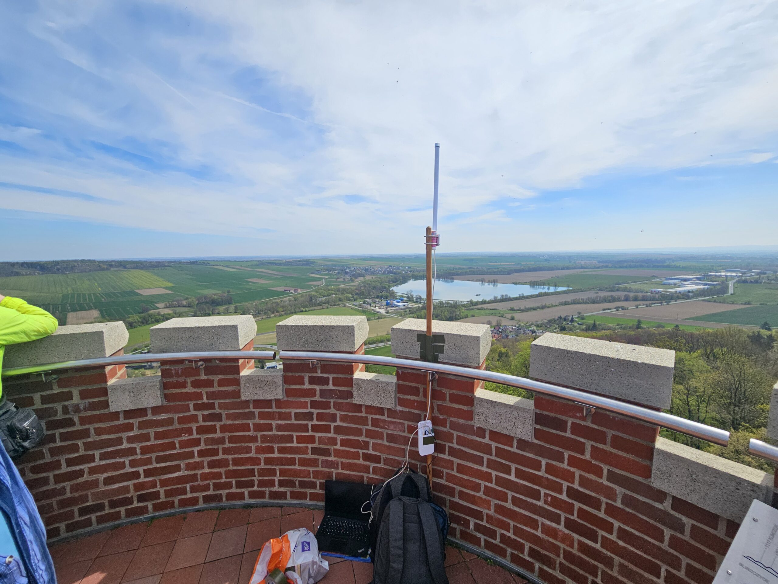
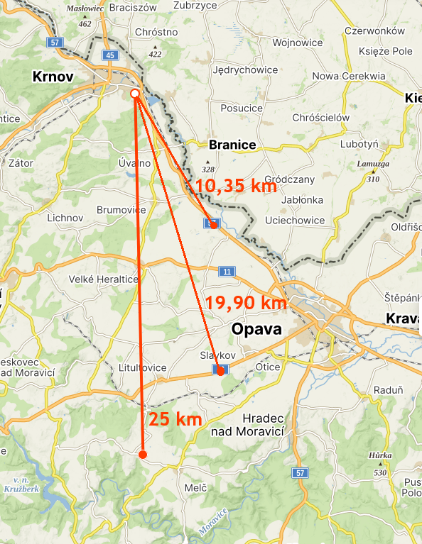
| Line of sight (gateway on Cvilín lookout tower) | 25 km | −93 dBm | 8 dB | 96.7 % |
| Line of sight | 19.9 km | −91 dBm | 8 dB | 93.3 % |
| Line of sight | 10.35 km | −89 dBm | 11 dB | 96.7 % |
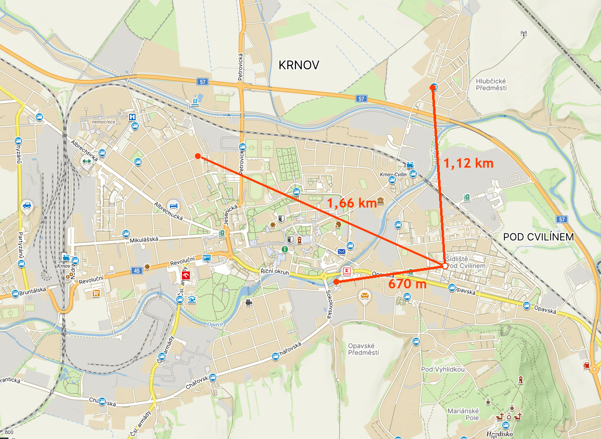
| Urban (gateway on 5th-floor balcony) | 1.66 km | −102 dBm | 2 dB | 83.3 % |
| Urban | 1.12 km | −89 dBm | 7 dB | 93.3 % |
| Urban | 670 m | −80 dBm | 4 dB | 96.7 % |
The 25 km result confirms that LoRaWAN at 2.4 GHz remains practically usable over distances of tens of kilometers, provided that direct line of sight between the end node and the gateway is maintained.
References
- Source code: https://github.com/diamondminer857/LoRaWAN-2G4-Node
- Original Mbed OS application: Sx1280-LoRaWAN-Test-App by MultiTech Systems
- Semtech SX1280 datasheet: semtech.com
- LilyGO T3 S3: TinyTronics product page
- MikroTik wAP LR2: mikrotik.com
- The Things Stack documentation: thethingsindustries.com/docs