
LoRa-169 is a complete LoRa system for the 169 MHz band, built at VSB – Technical University of Ostrava for teaching and for coverage measurements. It consists of battery-powered nodes, a gateway on the roof, a Raspberry Pi that forwards the data to MQTT, and Grafana dashboards.
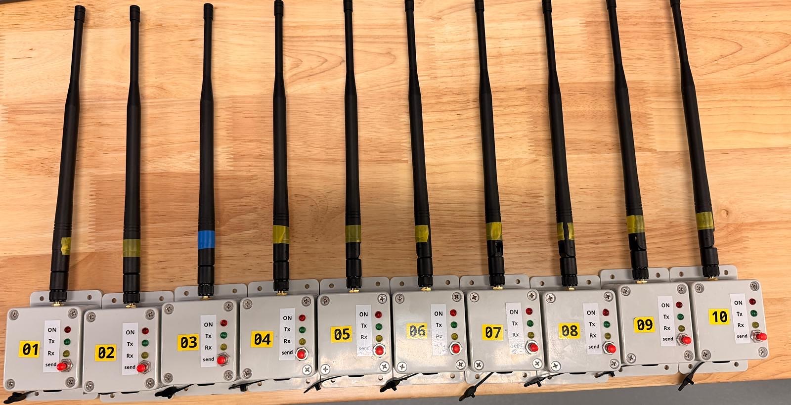
Hardware, firmware, software and the full documentation are open on GitHub: github.com/vsb-fei-440/LoRa-169. This page gives a short overview; every section links to the detailed description there.
How it works
- A node measures on a button press and sends three short radio frames with its ID, the measurement number, its transmit power, supply voltage and temperature.
- The gateway receives each frame and immediately answers with an acknowledgement (ACK) that carries the signal strength it measured.
- The node puts the strength of the received ACK into its next frame, so both directions of the link are recorded.
- The Raspberry Pi publishes everything to MQTT; Grafana shows one dashboard per node, one for the gateway and an overview.
More: architecture, radio frames and MQTT messages.
Radio settings
| Frequency | 169.4375 MHz |
| Bandwidth | 41.7 kHz |
| Spreading factor | 12 |
| Coding rate | 4/5 |
| Transmit power | up to +27 dBm (RFM98PW-169 module) |
Hardware
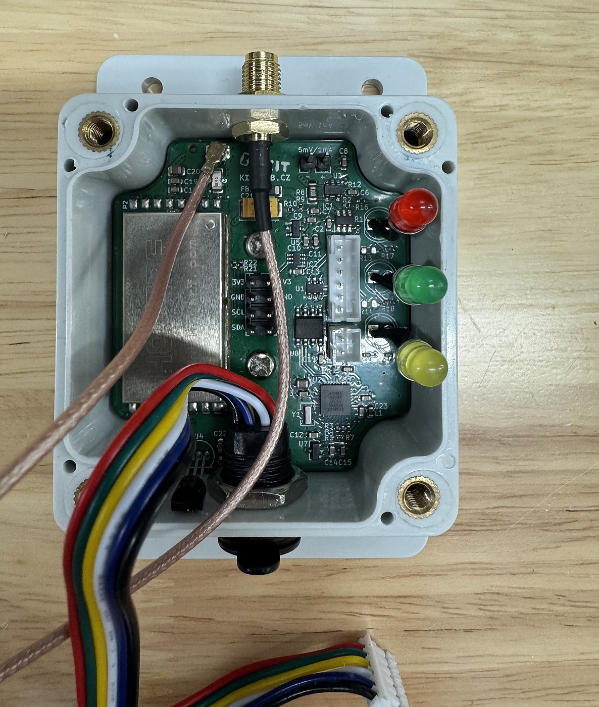
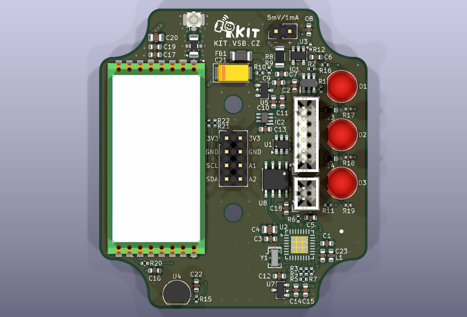
- Node – ATmega328P (Arduino Pro Mini compatible), RFM98PW-169 radio, DS18B20 temperature sensor, on-board current and voltage measurement, expansion header with I2C. Description, schematic, pin map
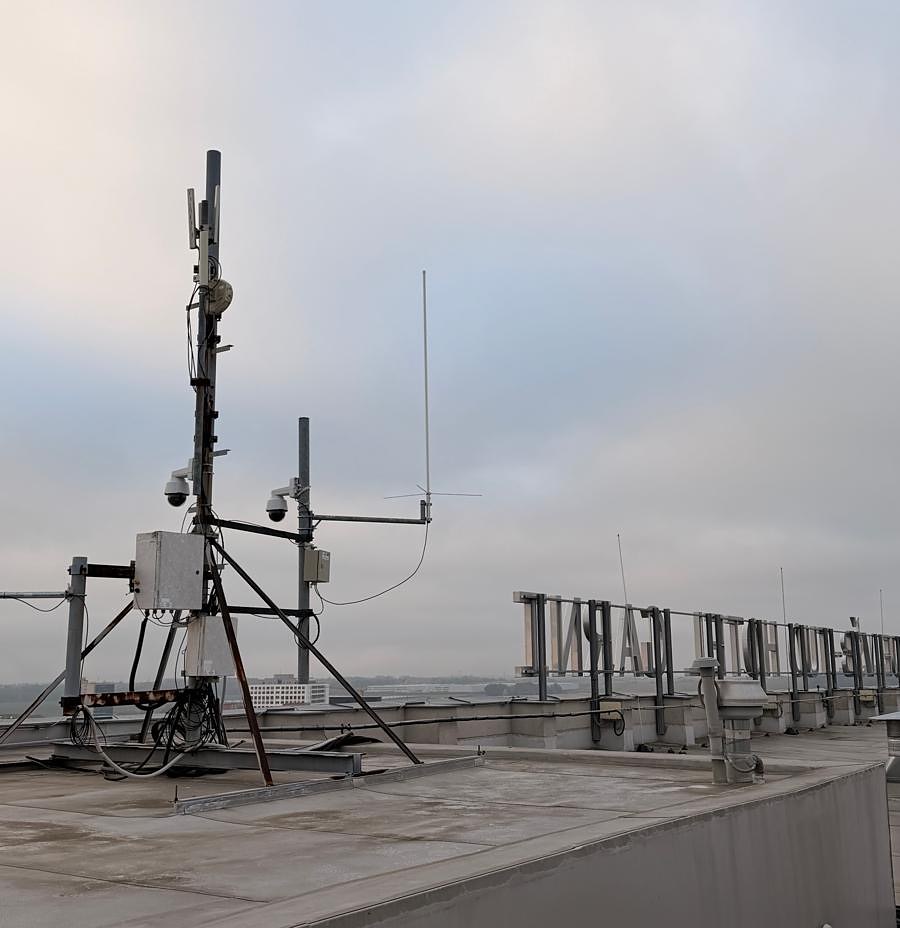
- Gateway board – two radio modules, one for receiving behind a SAW filter and one for transmitting, switched to one antenna; connected to a Raspberry Pi over USB. Description, schematic, pin map
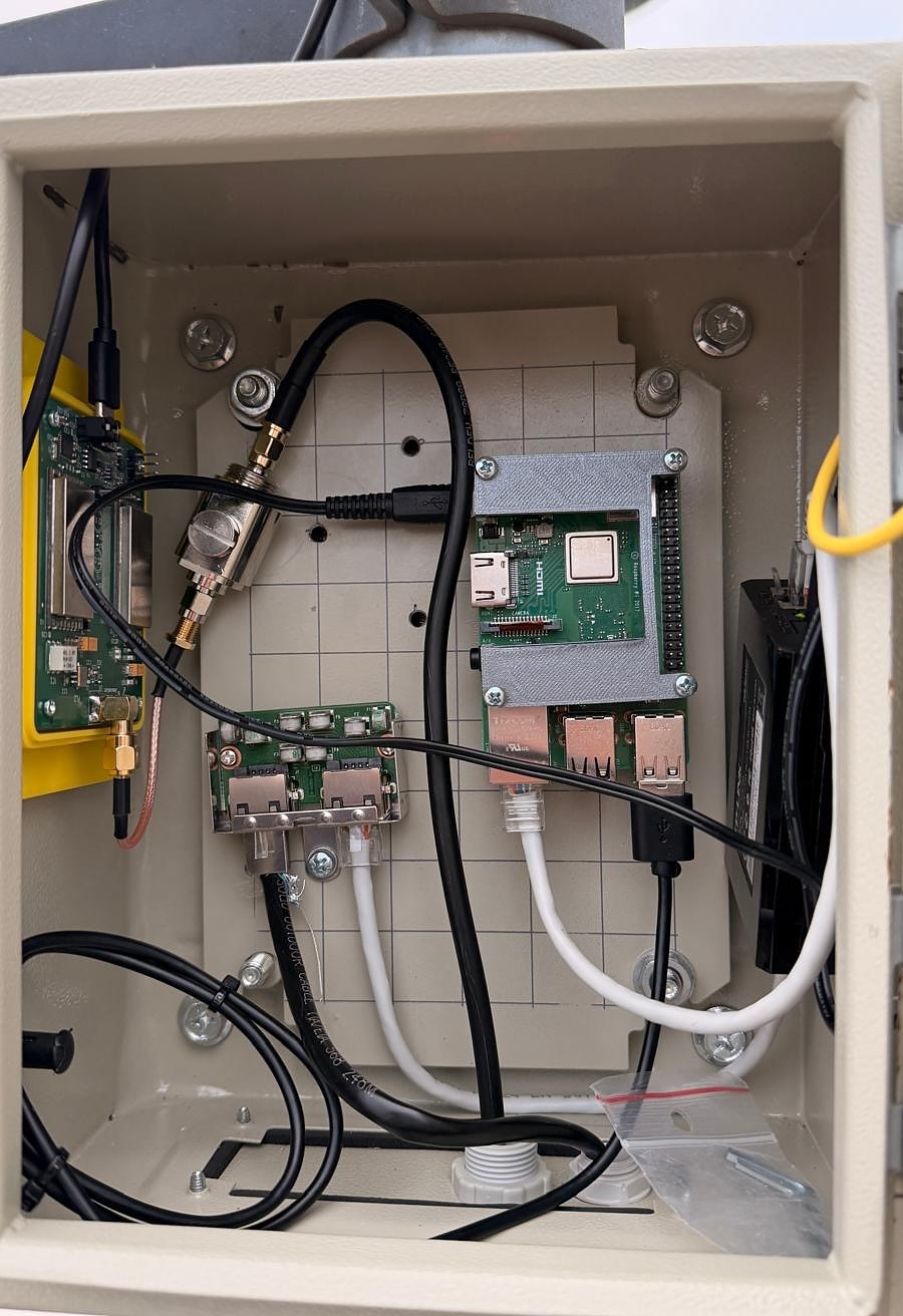
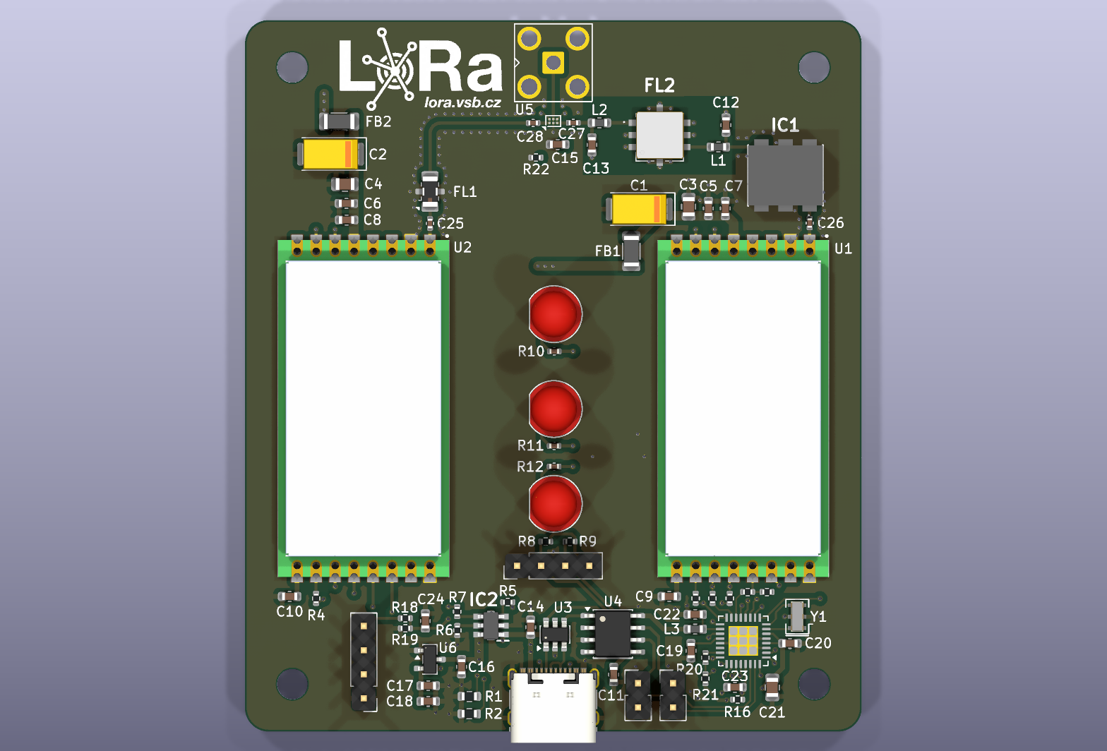
The gateway in more detail. A single LoRa module would have to share one antenna path for receiving and transmitting. The gateway board therefore uses one module per direction. The receiver sits behind a limiter and a narrow SAW filter (169.5 MHz, about 0.4 MHz wide) that keeps strong signals outside the channel away from it. The transmitter, with up to +27 dBm, sits behind a low-pass filter that removes its harmonics. An RF switch connects the antenna to one of them. The firmware guards the hardware: the receiver module can never transmit, the transmitter only transmits while the switch points to its branch, and the switch cannot change during a transmission. The board itself is a simple USB radio modem; all protocol logic runs on the Raspberry Pi, so it can change without touching the hardware on the roof, and even the gateway firmware can be updated remotely.
KiCad projects and production files for JLCPCB are in the hardware folder.
Software
- Node library LoRa169Node for the Arduino IDE with ten examples, from blinking the LEDs to the coverage measurement. Library and examples
- Gateway firmware – a USB radio modem with hardware safeguards. Gateway firmware
- Raspberry Pi bridge lora169-gw – forwards packets to MQTT, sends the acknowledgements, can update the gateway firmware remotely. Installation and configuration
- Grafana dashboards – one per node, gateway status and an overview. Dashboards
What the node is good for in teaching
The node is more than a radio. It measures its own current and supply voltage behind a shunt, so students can see how much energy each operation costs: transmitting a packet, listening for a reply, reading the temperature or sleeping. The library computes the energy in the background and can draw the current live in the Arduino Serial Plotter, so the peak of every transmission is visible. Ten examples build on each other:
- LEDs, button and power fault; DS18B20 temperature
- energy of individual activities and a live current plot
- sending and receiving, with signal strength, SNR and frequency error
- sensors on the switched I2C expansion header
- sleep and wake-up by timer or button
- a complete node cycle and the coverage measurement with acknowledgements
Frequency, bandwidth and spreading factor are fixed in the library, so students can experiment freely without leaving the permitted channel. Library, API and examples
Building your own
Start with Getting started: bootloader, first node, first gateway, Raspberry Pi and Grafana. Known issues and notes for the next board revision are in Known issues.
This page replaces the original 169 MHz experiment with an SX1276RF1IAS module, an Arduino UNO and a Raspberry Pi.